If this is your first visit, be sure to
check out the FAQ by clicking the
link above. You may have to register
before you can post: click the register link above to proceed. To start viewing messages,
select the forum that you want to visit from the selection below.
PLEASE CAN YOU SIMPLIFY THE LOCATION OF A 7909 WHERE I HAVE THE WELD IS POSSIBLE
WITH PHOTOS.
I did refuse 7909 use. but you can try it... I placed 7909 instead diodes VD8 and VD9, on their places (the diodes was been desoldered). photos I did not do.
my mod now... converter on LM2577-ADJ... if it is working good in Milelab so I think it will be working good in DP too
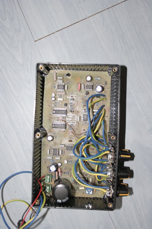
Clean the soldered side of the board with isopropyl alcohol, there is a lot of sh*t (residue) left after you soldered it. Also, you could check the connectivity (point to point) of your tracks, they don't look that good.
Also, check if you don't have shorted tracks.
HCF4338??
Please see the previous posts as well! My DP previously not worked. Reserve one of the two diodes is broken, the LF357 is also bad. I swapped it works. We measure the strength of the current flowing through the whole system without speakers. If you dare to over 180 mA (I think) of the FET is broken. The forum contains a lot of wisdom has been said before. Please take the trouble to read over. I do not know perfect English, but the google translator all of them to help (Although the Hungarian language is not like the Indo-European languages, so sometimes silly translation I get ...:-D Of course, this reverse is also true. The Indo-European languages in strict military order simple, Hungarian real life is like an old oak tree, three-dimensional fractal-like. German friends say that it is difficult to learn. I have a German. :-))
Please read through the forum. Everything is answered. I've succeeded. The head of my 450 uH, 2.9 Ohm. I'm using IRF840. A + E, - E measurement points to work. Easy to break down the diodes. Listen to this. Solder in the first two, which is 062 to go out and measure them. For me, one is broken and it was not good for metal detectors.
But first, be patient. I went to him three months (without the oscilloscope). :-)
I understand now works.
I did Sniffer XR 71 BUT NOT doing something good.sound works really be heard, TX power ok. trshold ok.volume ok, but the coil does not work does not react to metal.veliki pozrav from Serbia
hi just you set your multi meter in milli volt setting then check le 357 out put pin no. 6 to 0 volt ground if you have some voltage improve .......rajesh
I did Sniffer XR 71 BUT NOT doing something good.sound works really be heard, TX power ok. trshold ok.volume ok, but the coil does not work does not react to metal.veliki pozrav from Serbia
it works only half when turn threshold to middleposition and then activate tune button i can only reduce threshold a bit but not enough (but right potoentiometer installed)
irf740 get hot very quick
did you have an idea
or anyone else
\
There might be some other problems too, but A-A and B-B should be jumpered.
you need to set THRESHOLD in middle position and by RESET knob fully decrease the sound to silent.
hello kt315
it works only half when turn threshold to middleposition and then activate tune button i can only reduce threshold a bit but not enough (but right potoentiometer installed)
irf740 get hot very quick
did you have an idea
or anyone else
Great to see your reply for my message. I am attaching the image of the the PCB that I am talking about. Sorry I don't have Sprint Layout 5 installed on my machine.
-Ajay0707
I wrote it needs to be installed... I was not right. Sprint Layout is simplest CAD program you can find around and does not need to be installed.
at first, you have to convert the file JPG in BMP by any graphic editor that you use in your computer. I have did it in stead you now... you will find the BMP in ZIP...


Leave a comment: