hi, not on maximum. you have to choice intuitively a position of SECONDARY SAMPLE DELAY, like when you are tuning GEB in VLF detector, at first you switching it in ALL-METALL mode, then you take up and down a coil above and to a ground moving GEB pot. for every position of PRIMARY SAMPLE DELAY you have to find OPTIMAL SECONDARY SAMPLE DELAY position correspondingly. these tunings of both pots will assign the ground balance. for low value of PRIMARY SAMPLE DELAY you will have also low value SECONDARY PULSE DELAY, and hight for hight.
will give pics of the pin-pointer coil tomorrow because have not good lighten conditions now at night.
-
hiOriginally posted by kt315 View Post
i set 500k on minimum ( i set it complete on left position ) . so for reject the ground should change sample delay (500k )to max ?
regards
Edit :
thanks Kt315 , i buy 22mikro and add to my board .and say us about the my result .
can you put here data for pin-pointer coil ?
regardsLeave a comment:
-
test on gold ring with pin-pointer coil. PULSE WIDTH is set on minimum value, 150 us.

Leave a comment:
-
Caleb, ask any question. 2E2 is 2,2 Ohm. you can stand 2,2 2,7 3,3 3,9 Ohm at this place. 2,2 Ohm is
RED RED GOLD colors. ie 2 and 2 and 1/10. this value 22 to divide on 10... 22/10 = 2,2 Ohm.

Leave a comment:
-
I hate to keep asking small stuff but what is the band colors on the 2e2 r46 that's a hard one for some reason to find I only found 5000 at a time hopefuly I'm wrong.Leave a comment:
-
try to GRIPE OUT WHAT SECONDARY DELAY makes for. the time. do not be so dummy you are not.
the pot I called also RANGE and now GEB (ground enhanced balance).Leave a comment:
-
hi all guru .
why DP2 unstable in this soil , look these pics when i near these brick to coil have sound , when these brick have 10cm distance to coil have sound .
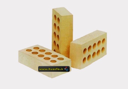

can anyone solve this problem , or it is natural ?( if natural it is bad to dp )
please guru solve it
regardsLeave a comment:
-
[QUOTE=kt315;185975]testing on screwdriver with a pinpointer coil. at the end I got some smoke from MOS-FET ))) fixed the problem... solder VD8 VD9 pads on both sides.
IRF740, DA1, the diodes are alive.
very nice
your coil is very Attractive , please say me about that .i see you use tl081 but better you use iron lf357 it is my idea.
if you can please add in your board fuse , better Protection.
and i see in your board TLC277CP , why you dont use Tlo62 or 082 .
please say me.
regards
AND i will change my pots like you , because i want finish my box.
have good time.Leave a comment:
-
that's kinda how I get my connectors anyway I just thought you had ones planed so if they fit use them or just solder to the board thanksLeave a comment:
-
testing on screwdriver with a pinpointer coil. at the end I got some smoke from MOS-FET ))) fixed the problem... solder VD8 VD9 pads on both sides.
IRF740, DA1, the diodes are alive.

Leave a comment:
-
Calebsone, you ask about type of connectors at PCB? solder wires directly to the board, I do not see a problem. connectors are standart type,
I take them from trash electronics boards - vga, svga, tv-sets. do not pay for components, take them from trash.
connectors for coil and battery are due same type like that stay in power supply's of personal computers. all are very ordinary standart types.Leave a comment:
-
KT for the connectors will any board mount to wire quick disconnect 2 pin work or do you have a place to find that exact one to fit the out line on the boardLeave a comment:
-
Inexplicably, now it works ... like a cat in heat, but it works ....
Leave a comment:
-
Measurements (IRF740 conected):
TR0 = 12.44v
TR1 = 7.06v
TR2 = 1.67v
TR3 = 1.66v
TR4 = 1.64v
TR5 = 1.64v
TR6 = 6.76v
TR7 = 7.04v
TR8 = 7.06v
TR9 = 1.57v
No sound, no detection...., what am I doing wrong ?Leave a comment:


Leave a comment: