Good Detector
Hi all,
A good PI machine must be follower to this table.
sorry for my bad english.
Happy new year,
Best Regards
-
delta pulse
Hello Ivconic , Check or monitor your total current from battery when adjusting your threshold , May Help to isolate problem. Start with small diameter coil first maybe ? Let us know what you find , My delta pulse is not finished yet. Merry Christmas and Happy New Year EugeneLeave a comment:
-
It is alive?!?!?


I just finished my fifth DP in this year.What to say? Somehow i feel satisfied
with progress i made building those.
Every of those five working very good from a start. No problems at all.
I reached the point where can be free to claim that my "machines"
are good and pretty accurate.
But i still have a lot of problems with coils!?
I just downloaded "Making a Fast Pulse Induction Mono Coil" from Joseph J.Rogowski
aka bbsailor.
Congratulations on such fine,neat and accurate theory bbsailor! I do agree 100% on
all you've been talked about.
I just made a coil; 26cm diamm. 25 windings, wire 0.35-0.4mm(close...i cant tell,i
busted my mickrometer last week)....Resistance of a coil is 3.3 ohms.
Buster is 2K2,frequency is 120Hz....
Results are good. 2cm coin it can detect on 30cm distance.I guess,it could be even
much better.
It is now in "experimenting" phase so i am not using any resistivity in serie with
coil....so it is just 3.6-3.8 ohms(including cable).
After 5-7 minutes, IRF740 is still cool!?
I am, sort of confused,amazed???
But there is a certain problem. "Playing" with Treshold knob, i can put device
in position to be unstable and "sing" like canarian???? Even than,detection is
very good,fet remains cold and nothing bad happened????
I am presuming it must be something about coil, resistance or dumper....
Between those five DP's i made,this last one is the very best...i have that
feeling. I also payed a lot of attention on components. I used mostly pp caps,
wherever it was possible.I used 1% resistors also....
It will need some more experiments to establish right values of dumper and serial
resistors,but so far it is acting very good.
Until now,all previous DP's needed coil with resistances over 6 ohms, to remain fet
calm and cool,this is first one working cool with <4 ohms coil.....so far.
I will experiment more,these days.If discover something interesting i'll post here.
regards
Merry Christmas and happy new year to all!!!Leave a comment:
-
Hi all.
For 1843. Check the power suply. If you use bat then maybe to be bad. Check the voltage as bbsailor wrote. If all are good then check for metals near the coil. In my lab when the coil is not at some critical position then DP sounds like canary (especially with full sensitivity and power). When is unstable check with the scope the power suply. Must be a horizontal line.
For Nelson. First make all measures that bbsailor says. If all are good check with scope pin1 of ic5. You must take a graphic like this from 1843 (the first). If and this is ok then ....to be continued....
Hi bbsailor.
Best wishes and mary christmas
Ohhh.... something yet for Nelson. Did you made a bridge between pin 2 and pin 6 of D8 :confused: (out 555)?? look your pcb.Leave a comment:
-
Check This First
1843
Look on the Mikron Delta Pulse Schematic at the +E and -E derived from the D7, D6 and D5 circuit across C7 and C8. Also look at the virtual ground that is at the output, pin-1 of D6A. Make sure that the proper +/-E voltages are on the voltage supply pins of all the ICs measured to TR8 or ground. If not, D8 or D9 may be bad. Make sure that everything with a ground symbol is connected to TR8.
I hope this helps.
bbsailorLeave a comment:
-
Problem in stability
Hi bbsailor & Geo,
In my DP when I put the gain pot at the middle or lower
It works stability, But when I increase the gain,it works instability and makes the canary sound.
I checked the pin1 of the IC5 with scope:
when the gain pot is at the mid:

When is higher:

Where is the problem?:confused:Leave a comment:
-
Delta pulse not working
Ok Geo and bbsailor.
Yes i do have a small osciloscope (radio shack that connects to PC).
I forgot, the DP has no sound when is on, and when i turn it off, i can hear a very low decresing tone.
I have an anmeter but not conected jet. I dont know if this could show me any signal stength instead the sound that for know is not working fine.
Regards and best Chrismas wishes to everyone on the forum.
Nelson
[
QUOTE=Geo;48391]Hi Nelson. The sound from coil means that 556 works, the oscillator works. Please tell me if you have oscilloscope to tell you what to looking for[/QUOTE]Leave a comment:
-
5 Ohm Damping Resistor?????
Nelson,
A 5 ohm damping resistor is wrong! 5 ohms for coil resistance is OK but the damping resistor should be a value between 500 ohms and 1K ohms (depending on the coil, coax length and MOSFET capacitance). Try making this change first...use a 1 watt 1K damping resistor.
bbsailorLeave a comment:
-
Hi,
My DP sound is like the canary sound and its detection is poor.
The frequency pot influences in that sound.
What is the problem?Leave a comment:
-
Delta pulse not working good
Hi Geo.
I finish my delta pulse from Mikron Schematics. I used the same PCB that you and Ivconic used. When i try to run the DP, a tone sound comes from the coil, and nothing from the speaker. Noice control meda some tone changes and intensity on the coil. I measure it with my EMD, and changes of intesity are show and also when i turn noise control to the maximun, damping resistor is getting very hot to the point it get smoke from it. Coil is 406 mH with 5 ohms damping resistor. VD17 led turns on a few seconds after turning the unit off, and then turns off.
No detection at all
What can be wrong?
I ll check diodes if the polarity is ok, dont know what else to check.
In advance many thanks
Regards
NelsonLeave a comment:
-
Hi bbsailor. Very good analysis but i believe that at detectors with large coil and low frequency as Delta Pulse there is not needing so critical timing and coil construction. All that you say are Very Important at small objects (as gold nudget ) where small times are needing . From my experience with different coils and medium objects (always the smaller object for test is a 25 mm coin and the bigger a pc box) there is not big diference if we will change the turns of a coil at 20%.
OK you will tell that the fine tuning makes the difference, but not at big objects.
Regards
Leave a comment:
-
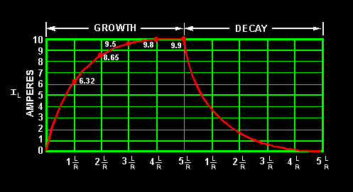
The amplitude of the back EMF pulse is based on the inductance of the coil (number of turns) and the current at the time of pulse turn off. The TC of a coil is calculated by dividing L in uH by R in ohms. Thus, a 500 uH coil that is 2.5 ohms has a 200 us TC. If the TX pulse width were variable between 200 to 600 us, the current would grow from 63.2 percent of maximum current to 95 percent of maximum current. The amplitude of the back EMF spike depends where on the curve the pulse is trurned off. Longer pulse widths allow the current to grow more and produce a higher amplitude back EMF pulse. You don't want the back EMF spike to go too much higher than the MOSFET voltage rating because the MOSFET is conducting/clamping the spike and the MOSFET will get hot.
The graph below is universal and applies to the current growth of all PI coils. Just measure your coil's inductance and resistance to find your coil's time constant and apply it to the curve below. You must also add the MOSFET on-resistance to the total coil resistance and any series resistors in the coil circuit. You must know the pulse width of your TX pulse to see exactly where on the curve your coil fits.
The Hammerhead 10 inch coil uses 26 turns of AWG 26 wire. The total wire length is 68.06 Ft. which is 2.788 ohms plus the .5 ohms on-resistance of the MOSFET (IRF740) for a total resistance of about 3.3 ohms. 500 uH divided by 3.3 ohms equals about 152 us. The Hammerhead pulse width of 10 to 75 us places the max current at about .5 TC or about 40 percent of max at 75 us. Carl designed the Hammerhead this way to keep the maximum EMF voltage spike below the MOSFET voltage while being sensitive (26 turns) to small targets.
You can see that there is room for some coil inductance and resistance changes to try to get the coil to operate higher on the TC curve for low conductivity targets (like small gold) along with lower delay settings. Make the coil with 300 uH (19 to 20 turns) of inductance (which reduces the EMF spike) and use thinner wire (wire wrap wire with thicker insulation), AWG 30 (5.5 ohms) with a MOSFET that has about 2.5 ohms on-resistance and you have a coil TC of about 37 us. At 75 us the current has almost reached 2 TC of about 86.5 percent of maximum. You can add a series resistor of a few ohms to get the same effect as using thinner wire using the same wire that you have. The only difference will be coil weight.
Where you want to operate on the curve is based on what types of targets you seek. Some types of metal can be fully saturated with eddy currents at lower TX pulse widths (lower TC), while other targets need longer pulse widths (longer TC) to obtain maximum target response.
Do some research on the time constant or decay time for the size and types of metal you seek so you can reverse engineer the coil and pulse width range to be optimum for you desired targets. Remember, one design cannot be optimized for all targets.
I hope this helps.
bbsailorLeave a comment:
-
 Guest repliedHI Bbsailor !
Give a more dept If increase a amplitude of the back EMF spike at both ends of the pulse width range from 400V to 800 V ???
Give a more dept if PI detector work whit bipolar transmited pulses???Leave a comment:
-
Removing Turns: A few things will change
Nelson,When you remove coil turns, a few things wil happen.1. The coil resistance will drop slightly as each turn is removed.2. The coil current will increase slightly as each turn is removed.3. The peak back EMF spike will be less as each turn is removed.4. The induatance will be less as each turn is removed.5. The current ramp up Time Constant (TC) will change as both Inductance and Resistance is changed, TC=L/R (L in uh and R in ohms = TC in us). A pulse width that is 3 TC long will achieve 95 percent of maximum current. You should measure the things I suggested to better understand how your coil is working. Most improvements occur when a few things are changed. Coil turns, coil diameter, pulse width, TX frequency and coil current need to be balanced to achieve good detection depth, a good response from your coil sweep speed and a reasonable battery life.bbsailorLeave a comment:
Leave a comment: