Announcement

Collapse
No announcement yet.

STM32 controlled PI detector

Collapse
X
 
  • Filter
  • Time
  • Show
Clear All
new posts

  • #46
    Now I have another doubt, as my Stm32 is powered this way (VDD = power supply GND and VSS = power supply -3.3v), to give the preamp signal to the ADC input, I need to create a centered reference of 1.65v, should this 1.65 be positive or negative relative do circuit GND, so the ADC can read it properly?

    Thanks.

    Comment


    • #47
      The value must be negative (-1.65V) with respect to GND.

      Comment


      • #48
        Originally posted by eduardo1979 View Post
        The value must be negative (-1.65V) with respect to GND.
        Thank you!

        Comment


        • #49
          I got a much better sensitivity now after reducing the sample width from 10us to 5us. So that explains that my main problem is noise?
          Enjoy the videos and music you love, upload original content, and share it all with friends, family, and the world on YouTube.

          Comment


          • #50
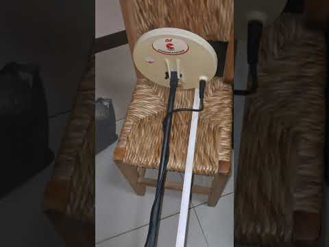
            Some more tests: https://www.youtube.com/shorts/SNQcJdVVXW0

            Details
            Hardware: Power supply, TX and preamp almost the same of Goldscan 5.
            Coil size: 23cm
            Freq: 2.6khz
            TX pulse width: 100us
            Sample pulse delay: 10us
            Sample pulse width: 5us
            Analog demodulation driven by 4066 with software controlled timings
            ADC reading from the output of TL072 sampling integrators
            No GB nor EFE subtraction yet. Just the main sample with software average driving a PWM VCO.
            Audio output: piezo buzzer
            MCU: Stm32f407vet6 dev board

            Some results:
            - 1 euro coin: 28cm
            - 2.4 gram 18k gold ring: 26 - 28cm
            - 0.9 gram gold nugget: 10 - 12cm

            Would you try to get more performance (distance / depth) or is it better to go further to the next steps now (GB, etc)?

            Thanks.
            Enjoy the videos and music you love, upload original content, and share it all with friends, family, and the world on YouTube.

            Comment


            • #51
              Actually I use only one integrator + gain before the ADC as I am reading only the main/target sample.
              To add the other samples (GND early, GND late, EFE) and considering that I want to do all the calculations on the software, is it better to add an independent integrator for each kind of signal (one integrator for GND early, another for GND late, other for EFE) and read them in separate ADC channels or is it better to just keep using only one integrator and just reset it with some kind of switch after each sample to prevent any residual signal from the previous sample to leak to the next sample?

              Thanks.

              Comment


              • #52
                Here are some more tests. For now Im planning to use the detector only in the beach, so no GB is required, just an EFE sample subtracted in a differential integrator.
                I built a web page just to test some parameters live in the PC before moving to a rotary encoder / screen.


                Testes done with a GPX 5000 coil with house ambient electric noise.
                Distance for a 2.4g 18k gold ring - 32 to 36cm
                Distance for a 0.9g gold nugget - 14 to 16cm

                Dont know if when I made a pcb for it, the performance will change much.
                 

                Comment

                Working...
                X