-
Don't waste your time. You need to make a sensor with shielded coils and minimal received signal. Then remove the capacitor c33 10 nanofarads. In its place, put one or two capacitors that give the maximum received signal without moving the coils relative to each other. Try with a piece of ferrite, a small change of c33 may be necessary. A signal from any metal should be received when entering the sensor. If the signal is when leaving, swap the beginning and end of one of the coils.Leave a comment:
-
From before, xx years ago, when I did a lot of coils for TGSL/IGSL...
I know from experience that the inductance of the coils changes significantly when the windings are brought close together and tightened with thin string, or wrapped with tape.
In this case, they are coated with superglue.
And it is very difficult to predict the final inductance.
It's one thing when the windings are just wound and the other is when they are tightened and arranged.
Of course, resonance can be fixed with capacitors.
But the difference of 0.6mH does not seem like a good minimum "jitter" to me and I will try to wind better and more precise coils.Leave a comment:
-
I agree. But in my case, glasses with a higher diopter are needed!Originally posted by scs-bg View Post
Age takes its toll and I totally overlooked what you pointed out a while ago.
Yes, exactly.
Even though I wound the coils on the same former... it's obvious that I was wrong in the number of windings, because 5.2mH and 5.8mH is a HUGE difference!
And the previous video I tested with floppy disk micro coils worked fine; JUST BECAUSE those two micro coils are 100% identical in both inductance and resistance!
The coils are wound by hand, it's a monotonous job, I have a lot of distractions from the side (someone is constantly entering and leaving the room + 6 cats and 2 dogs blow up the house) and
I probably "over/under counted" and didn't do both coils with exactly 110 windings.
It is difficult to work in these conditions.
The tomcat jumped on me from the top of the closet and dug its claws into my back!
I spoiled him and it's a game for him.
I guess I was wrong in the number of windings then... hard to tell!

Leave a comment:
-
TX amplitude and clarity are superb!
Congratulations Sasho!
The amplitude goes over 30vpp!
This TX is very applicable in other projects as well.Leave a comment:
-
The tuning is around resonance. I warned you that it takes experience and knowledge of the theory.Leave a comment:
-
Before you do a test, did you do a ground balance? Otherwise it will not work properly!Leave a comment:
-
Test around this integral with other elements and see if it has any effect and rotate the trimmer.Leave a comment:
-
Try both variants - either to swap the beginning and end of the terminals of the receiving coil, or to turn it 180 degrees and balanced it again, connected as it is, without swapping the wires.Leave a comment:
-
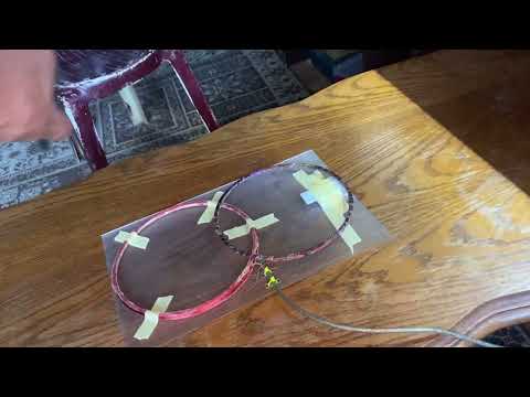
The coils are made according to the specs in the schematic.
Except the thickness of the wire is not 100% identical, I just didn't have the right wire gauge.
TX is ~5.2mH and RX is ~5.8mH ... in that range. TX is 10 ohms and RX is 28 ohms.
Whatever I do, however I twist the wires; it always behaves the same: it does the opposite.
High tone to irons and low tone to non-ferous!?
The previous video with those two small coils (from an old floppy disc), just for testing purposes; it worked properly.
Now with a coil with more correct specs; it won't work properly at all.
Here the balance of coils so that the signal on the RX is minimal; it obviously doesn't produce results.
I will have to replicate the situation with those two micro coils from the floppy disk and do the comparative measurements again.
In both cases, I forgot to measure the frequency as well.
I think I'll have to wind another coil, either TX or RX because I obviously did something wrong here?
The last time I DIY coil for VLF-I/B was 15-18 years ago, now I understand why!
In the meantime, I forgot all the "beauty and magic" of DIY such coils!

Leave a comment:


Leave a comment: