Originally posted by gurdal
View Post
Ok, now;
use oscilloscope,
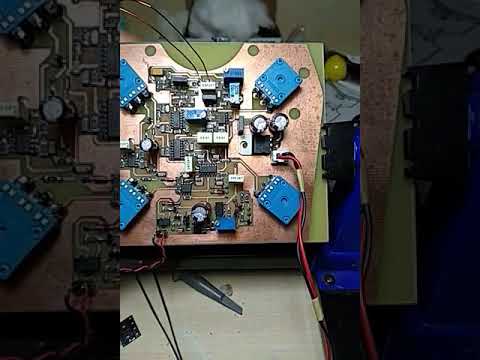
attach probes across TX coil and with trimmer R12 100 ohms ("AMPL." on pcb) adjust TX amplitude and waveform to good sinus and somewhat between 12Vpp to 16Vpp.
First turn DISC potentiometer at "3" or 1/3 of the full turn scale.
Than use piece of mineralized brick, pottery, stone... or (worst solution) very small piece of ferrite and with it swing ~ 5-10cm above the coil and with R16 46k "GEB" trimmer try to adjust no response on it at all.
Situation with GEB is a bit complicated since i added also a trimmer 10K, so you to be able fine to calibrate GEB potentiometer range.
Trimmer R21 10K ("Phase" on pcb) is there to fine readjust phase before switching.
Use different metals and test how it adjusts.
R50 is 180 ohms. When you turn Sense potentiometer R34 1k at maximum sensitivity AND it is still not chattering ; you can lower R50 from 180 to 150 or even 100 ohms.
Experiment.
With Sense potentiometer at maximum sensitivity; it is allowed detector to produce very rare chatters, no problem, normal.
But first of all; i asked you several times and this time i will ask for the very last time;
VOLTAGES? Measure all the power supply voltages and report here!
At LF347 4. pin is Vcc and 11. pin is Vss.
At dual dil-8 opamps 8. pin is Vcc and 4. pin is Vss.
At single opamps 7. pin is Vcc and 4. pin is Vss.
Referent point is ground, when you check voltages at those pins.
Ground is 1. and 2. pin at LM358.
Put "BLACK" probe of voltmeter at 1. and 2. pin of LM358 and with "RED" probe of voltmeter check all the power supply pins i listed above.
If you don't report voltages on your pcb any sooner... i will have nothing else to talk to you.
I horibble dislike to repeat same questions all over again.
Without proper voltages; your detector will never work as it should.
Regards!



Leave a comment: