
not used by Minilab engineers? = no idea, I know that phase shift in IB detectors is used for VDI calculation, why not apply that in PI ?
-
Hi pito,
If using of two channels will gives possibility to stable discrimination in PI MD, do you think that this is not used by Minilab engineers?Leave a comment:
-
" what phase" in PI MD. =
You have two channels in GOLDSCAN 4, so there will be a phase shift between them,.....
Maybe that can be used for discrimination???Leave a comment:
-
Changing of the tool not change the mats of the process!=
summing
- 5V + 5 V = 0V
magnitude
√ (-5)² + (5)² = 7VLeave a comment:
-
ATMega328BP - this one letter "B" gives you an additional 2 x 16b timers with full external access.
Pololu has it on its modules - Extra
!Leave a comment:
-
Hi ivconic,
Yes, my question to pito is also " what phase" in PI MD.Leave a comment:
-
The reduced range is due to mixing two channels. = instead of mixing we can calculate the magnitude and phase using stm32
Changing of the tool not change the mats of the process!Leave a comment:
-
Pito, now let me answer your frequent intrusions regarding the implementation of mcu, which would replace a lot of "hardware" on the detector.
Now that we have a timing "scheme" and a proper schedule of when what works; nothing easier than writing mcu code that will do it without problems.
But that's not the point. The point is to go slower (and the harder way); in order to fully understand the entire process that takes place in such a detector.
Only when we have a full understanding of the processes taking place there; then we can play around and convert the hardware piece by piece into code.
Unfortunately my favorite Atmega328P doesn't have enough resources to generate 4 pulses on 4 separate pins and do it all flawlessly accurately.
By the most stupid method "digitalWrite pin..." and so one after another all 4 pins... is a child's toy, which will not work well.
Because the final goal here is the shortest possible sample delay and the most precise timing.
A single C function can take too much time for such tasks.
Direct port/pin manipulation with (or without) interrupts can be up to 12 times faster.
But still not enough for such a delicate task.
Ok, that's all great when we make a detector that is a child's toy with a delay greater than 50uS and timings that will have a smaller or larger jitter at each clock.
The internet is full of such attempts. And on this forum you have "a dozen" attempts in that style.
It's all child's play, good for educational purposes, elementary education and entry into the world of programming.
But if I want a PI detector with maximum 10uS sample delay and very precise timing; it takes much more than that.
Perhaps something more could be extracted from Atmega at the lowest level, using pure assembler. But even then it wouldn't be good.
Ok, STM32, ARM... that's a better story.
And that can be done.
But we are far from that, this detector has not yet shone with its full glory. There are still a lot of tweaks to come until then.
I will always have a good laugh at one of Carl's "free thoughts" that he unwittingly and unintentionally wrote... and it has something to do with this!
When he was explaining on another topic how easy it is to solve this kind of task; he said (I'll paraphrase, it's not verbatim): "I'll choose a mcu that has at least 8 to 16 timers and that's it..."

Carl the GENIUS!

Leave a comment:
-
And of course, as an aid in understanding (experts don't need this) timing operation:
Leave a comment:
-
Only things that I have changed from the last time:
1) PPS rate now is 1000 Hz.
2) IRF840 is now with heatsink
3) Damper is now 470/5W
4) previous 2R2 is now also 5W.
Heatsink is lightly warm ... but far from being hot.
470/5W is super cool, previous 2x1k/1W were warm to hot after 10-20 minutes, same as previous 2R2/2W.
Could it be that power consumption dropped so significantly (from 220mA to rock solid 150mA) just because I put much "stronger" resistors which are now totally cool?
This is INTGRIGUE!
Quite opposite from what is to be expected when changing PPS from 500 to 1000Hz... or am I wrong?
Leave a comment:
-
@ Carl,
My BAD!
Shameful!
I completely forgot to check RV2 and it was not completely closed, that's why shortest possible delay in previous case was "≥ 30uS".... WRONG!
Now when I turned RV2 to 0 resistance; situation has changed, actual shortest possible delay on original GS4 setup is "≥ 10uS" and that's now correct!
...
Also noticed one more thing, previous confusion about peaks of pulses... scoping only Q4 gives amplitude slightly over 8Vpp.
Adding second pulse (via 10k) is decreasing it to 6Vpp and so on. Q4 with all 4 other gives as on above photo 5Vpp.
And that part now is clarified. But Q8,Q7,Q6 and and Q5 still remains at ~1Vpp ???
I changed PPS down to 380Hz and nothing has changed, still all 4 are ~1Vpp. Misty??
...
Anyhow, now with shortest possible delay, 1000PPS, GND mode, smallest coin is detected much better, clearer! Bingo!
And there is another "intrigue" to solve, Carl you try to explain this; 1000PPS....all as you see on posted photos and yet overall power consumption with loudest detection is rock solid 150mA ???
How come?
This is "battery saver" solution! What if... 2000PPS... and more?
...
Probably as I adjust wider pulses the consumption will rise a bit...
...
Fun! Fun! Fun!

Leave a comment:
-
One thing confuses me, however.
Last time the pulses on the gates were 4Vpp while on Q4 it was around 3Vpp and now that has changed and now the pulse on Q4 is around 5Vpp and on the gates it is 1v ???
Last time I monitored 3 pulses simultaneously and now all 5.
Last time it worked at 500PPS and now it works at 1000PPS.
What of all this is the reason for this change???
Leave a comment:
-
Ok, 10k gives me 890-1300 Hz !!! Wow!
Behavior of the detector hasn't significantly changed... except this; with loud audio detection overall power consumption now is .... 150mA !?????? WTF???
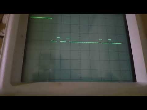
Carl you gonna love this; yes you are right, all 5 pulses can be scoped at the same time!
Here is the Delay behavior and timings:
Leave a comment:
Leave a comment: