Announcement

Collapse
No announcement yet.

LOOKING FOR GOLDSCAN 4 Schematic.

Collapse
X
 
  • Filter
  • Time
  • Show
Clear All
new posts

  • Jose
    replied
    Originally posted by amarasha View Post
    hello jose
    i made gs4 and there are a problem with -5v. when turn on +5 and -12 are correct but -5v is -10v. when i separated tl074 -5v is correct.
    what can i do for this problem. i tested and not found any shortcuts.
    thanks
    Hello Amarasha
    Regulator (-5Volts) would have to maintain stable voltage level regardless of current consumption.
    I can only make some guesses.
    Check the correct installation of the 79L05. Can be inverted. See the catalog of fabicante.
    Replace the regulator 79L05, by another 7905 to see if that solves the fault. I and had problems sometimes with 79LXX series.
    Verify that this installed and in good condition 22 mf capacitor this output to the 79L05.
    Hope this helps. Jose

    Leave a comment:


  • amarasha
    replied
    -5v problem

    hello jose
    i made gs4 and there are a problem with -5v. when turn on +5 and -12 are correct but -5v is -10v. when i separated tl074 -5v is correct.
    what can i do for this problem. i tested and not found any shortcuts.
    thanks

    Leave a comment:


  • ABDW9
    replied
    Originally posted by Jose View Post
    Davor and Porkluvr Thanks for clarifying these issues.
    ABDW9, if you have oscilloscope check the noise level at the output of 5534, with the coil disconnected. If noise is high for some reason, the detector becomes unstable and impossible to tune.
    Best Regards
    Jose
    Hello again
    Well I will do
    And tell you participate next
    Thank you for your attention
    Greetings

    Leave a comment:


  • alonejax
    replied
    hi to all

    any body make gold scan 4?
    what is max sence meter for gold in dept? is a good detector?
    thanks

    Leave a comment:


  • Jose
    replied
    Davor and Porkluvr Thanks for clarifying these issues.
    ABDW9, if you have oscilloscope check the noise level at the output of 5534, with the coil disconnected. If noise is high for some reason, the detector becomes unstable and impossible to tune.
    Best Regards
    Jose

    Leave a comment:


  • Davor
    replied
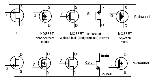
    BF245 is by definition a symmetrical one. It is easier to find it here than the J parts.

    When mentioning the diode test, next time check the barrier voltage ... it is lower than the usual silicon diodes, as they are not doped as much. May come handy sometimes.

    Leave a comment:


  • porkluvr
    replied
    Originally posted by Jose View Post
    KT 315
    In post # 4 you could see in this way the location of the drain and source.
    Anyway, Geotech forum members, saying that small signal configurations as in this case, drain or source can be connected either up or down.
    Regards
    Some manufacturers will tell you if a particular JFET has interchangeable S & D. Other manufacturers will have the "identical" part number but their data sheet will say nothing about S-D interchangeability.

    For instance, the Philips (NXP) and Fairchild data sheets, state "S & D are interchangeable" for the J111~J113.
    Vishay's J111~J113 spec sheet, however, makes no mention.

    Another way of stating S-D interchangeability is "symmetrical".
    Not all JFETS are symmetrical. Do not assume that all JFETS are symmetrical just because some of them are.

    2N4393 looks like it may be a good sub for J113 and Fairchild's 2N4393 datasheet does state S & D being interchangeable.

    EDIT: So, what this all means is that if you are doing a PCB layout and run into a problem with a J113, you can sometimes side-step the issue by making a pin-swap.

    You can get an ohm-meter and measure from G-D and G-S and you should get identical readings. Same with a diode test.
    Attached Files

    Leave a comment:


  • ABDW9
    replied
    Originally posted by Jose View Post
    Check the PCB that the "D" of J113 in both channels are connected to GND.
    Jose[ATTACH]24235[/ATTACH]
    Hello
    Brother josie you beautiful greetings
    I have searched in connection j113 and grandmother fully connected
    Congratulations I wish you.

    Leave a comment:


  • Jose
    replied
    KT315, from the point of view of Fet electrical symbol, you are right.
    We would have to see if it was error to draw the diagram, sketch on paper.
    Jose

    Leave a comment:


  • Jose
    replied
    Originally posted by petoco View Post
    Hello Jose,

    I just finished mounted the GS4 every thing goes ok, but when I made the test in my house when I swept the search head one side to another it made a fake signal, like when it find a metallic object, if I put on the floor the detector stabilized well if not a reset and it work properly. I ask to you because I read in your post 150 i think, you faced this problem too? you manage to solve it. I am trying several things but cant fix it, I thing the problem is in the coil and I would like to try your double coil on post 171, but I don´t know what is RG59, it refer to the circuit conection? another question is if you eliminate R14 or not?.

    Thanks in advance
    Petoco
    RG59 coaxial cable is connected between the coil and the detector
    R14 and R79 are 1K, 500 ohms in paraleo way, you can remove and place a resistance equivalent.
    The final value of R buffer (R14 and R59) depends on the type of coil.
    The spurious signal in the coil, can be caused by inadequate shielding.
    You may also minerals in the soil, brick or ceramic.
    Try detector in the field and see how it behaves in different terrain.
    Regards

    Leave a comment:


  • kt315
    replied
    ooh main God... why you so are disliking the electronics...

    Leave a comment:


  • Jose
    replied
    KT 315
    In post # 4 you could see in this way the location of the drain and source.
    Anyway, Geotech forum members, saying that small signal configurations as in this case, drain or source can be connected either up or down.
    Regards
    Click image for larger version

Name:	DoS.GIF
Views:	1
Size:	6.2 KB
ID:	335714

    Leave a comment:


  • kt315
    replied
    it is not D/Drain of J113. I see S/Source transistor pin on the schematic you marked. Drain pin is above.

    Leave a comment:


  • Jose
    replied
    Originally posted by ABDW9 View Post
    Hello Jose
    Now only key "RESET" just is not working??
    .......................................
    All the problems that I have a solution
    Thanks Only Jose
    Check the PCB that the "D" of J113 in both channels are connected to GND.
    JoseClick image for larger version

Name:	GS4 GND.JPG
Views:	1
Size:	49.7 KB
ID:	335713

    Leave a comment:


  • petoco
    replied
    Hello Jose,

    I just finished mounted the GS4 every thing goes ok, but when I made the test in my house when I swept the search head one side to another it made a fake signal, like when it find a metallic object, if I put on the floor the detector stabilized well if not a reset and it work properly. I ask to you because I read in your post 150 i think, you faced this problem too? you manage to solve it. I am trying several things but cant fix it, I thing the problem is in the coil and I would like to try your double coil on post 171, but I don´t know what is RG59, it refer to the circuit conection? another question is if you eliminate R14 or not?.

    Thanks in advance

    Leave a comment:

Working...
X