Announcement

Collapse
No announcement yet.

Tesoro Lobo news

Collapse
X
 
  • Filter
  • Time
  • Show
Clear All
new posts

  • perdica 2
    replied
    Originally posted by zoomix View Post
    Vur prédica2,

    I tried to check the phase of -12 but my scope has only one entry. I think the best would be to a phase meter to control ^. I found several schema.

    My knowledge of analog electronics are limited, but I try to understand. I see that you work on a simulator and thank you for your help.

    The results are good. -I change the capacity for a 25nF TX and I can turn the gain up.

    Another important finding was correct discrimination has always 24Nf with 470K on R10. The discriminated of ferrous as well as in an area of ​​1.5 cm was located 35 cm from the coil. This area was moving according régalge GB

    try R10 180k and more ,no RX cap added and no changes on pre amp


    try R10 180k and more ,no RX cap added and no changes on pre amp

    Ferrous metals are correctly discriminated and never rings. The legacy currencies in oxidized steel rings again showing that discrimination works well. 200K on R49, 51K between R11 and pin 7 of U4B. Iron is discriminated with the potentiometer is 30%

    I also think that the GB is correct. We must find the right setting of the potentiometer on the PCB.

    Can you Comfirmed your last message:

    In your simulator, you advise on R10 to 180K and connect pin 5 and 6 U5B together and to ground? No capacitor on RX?

    With that, I'd discrimination in a phase shift of 30 ° to 180 ° with Rx as a reference signal? is that correct?

    What you call "amp" ? it's pre-amplifier consists of all OP amplifier located before the BF245?
    1.about U5B ,SORRY i was basing on a previos posteted schematic where pin5 was grounded,
    the FOMA and W.LAHR have right conections with pin6 grounded, sorry!!
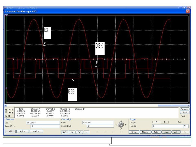
    -with R10 100k on sim. when you tourning disk.pot. a some kind of jumping was apearing on phase , but with biger value of R10 (150k and more ) has a good shift of 30-180deg
    2.if you see on my picture the GEB channel is is on 0 DEG reference to RX signal measured at the output of the pre-amp (pin 1 of U7A) ,and if you see when it rise,it make slite curve whitch narrow the the accept region from -80 to +90 (narrows 180 to 170 deg),thats becouse to reject ferrite and ferromagnetics materials
    - the center of accept region is 0-DEG
    - with 30 to 180 on disc channel i refer to that ,the center of disc channel goes from 30 to 180 ref to RX signal measured at pin 1 of U7A
    3.the pre-amp i call ,everything from input ay C4 to output at (pin 1 of U7A),
    -yes ref signal is measured at the input of bf245(tis75)
    -RX CAP i refer to parallel cap with coil
    -try to get good sine on tx ,without good sine it makes huge changes at at GEB and DISK
    -W.LAHR schematic it looks best with one mistake R14 from 1k ->10k (R10 sel.)
    Last edited by perdica 2; 04-15-2012, 08:48 AM. Reason: zaborajv

    Leave a comment:


  • zoomix
    replied
    PHASE METER

    Vur prédica2,

    I tried to check the phase of -12 but my scope has only one entry. I think the best would be to a phase meter to control ^. I found several schema.

    My knowledge of analog electronics are limited, but I try to understand. I see that you work on a simulator and thank you for your help.

    The results are good. -I change the capacity for a 25nF TX and I can turn the gain up.

    Another important finding was correct discrimination has always 24Nf with 470K on R10. The discriminated of ferrous as well as in an area of ​​1.5 cm was located 35 cm from the coil. This area was moving according régalge GB

    Since I switched to 25nF, the area disappeared.
    Ferrous metals are correctly discriminated and never rings. The legacy currencies in oxidized steel rings again showing that discrimination works well. 200K on R49, 51K between R11 and pin 7 of U4B. Iron is discriminated with the potentiometer is 30%

    I also think that the GB is correct. We must find the right setting of the potentiometer on the PCB.

    Can you Comfirmed your last message:

    In your simulator, you advise on R10 to 180K and connect pin 5 and 6 U5B together and to ground? No capacitor on RX?

    With that, I'd discrimination in a phase shift of 30 ° to 180 ° with Rx as a reference signal? is that correct?

    What you call "amp" ? it's pre-amplifier consists of all OP amplifier located before the BF245?

    Leave a comment:


  • perdica 2
    replied
    picture of sim based on posted schematic

    Leave a comment:


  • perdica 2
    replied
    ZOOMIX do you have disc???????????????

    i think you can adjust for all-metal but how is the disk?
    if you see other tesoro models on SIM the disk goes from 90 to 180 deg ref to RX signal

    i have simulated disk of both lobo schematics with or without added resistors the disk goes
    from -120~-100 to -20 ~ 0 deg ref to RX sig no rx cap added and no changes on pre amp
    i think the GEB is fine

    try R10 180k , switch 5th and 6th pin entries on LM393 ,with this changes you can get disk
    from 30 to 180 deg ref to Rx signal ,no RX cap added and no changes on pre amp
    Last edited by perdica 2; 04-13-2012, 12:13 AM. Reason: mistake

    Leave a comment:


  • perdica 2
    replied
    acording to this schematic
    with RX 10mh-22n-20kh (10 kh resonance give -12 deg)
    28mh 8.6n 20kh

    Leave a comment:


  • homefire
    replied
    William Lahr Schematic.
    Attached Files

    Leave a comment:


  • zoomix
    replied
    révision of my other message:

    all schématic of foma don't give the good connection on G.B and dicri. For the good connection G.B and discri see scheamtic W.L 6/90

    For predica 2;

    sorry but I did not understand your message. You advise me to go down to the value of 24nf to 22nf for have -12 ° phase shift ???


    best regards...

    Leave a comment:


  • zoomix
    replied
    Lobo it's ok...BIG MACHINE

    Hi,

    Thank you Eugene. There is the website redram give very good information and result on vidéo.

    But all schématic of foma don't give the good connection on G.B. For the good connection G.B see scheamtic W.L 6/90

    For my tests:
    I improved discri with 470k on R10 (visible on a foma schematic).

    Yes Predica 2, i work with 22nf on Rx because this coil is 28.15 mH 50.5ohm.
    I dont want 28.15mh but after make 65tr of 0.28mm and like foma's schematic i mesured with ohmeter 50.5 ohm. After i make a essential LC meter for mesured coil and discover this value

    Your value is correct
    i have theoritical value with formule of thomson 159/racine(LC)
    24NF for 20Khz
    31.5 for 17.5khz

    I try other test because I think that is great machine

    Thank you

    Leave a comment:


  • amtech2005
    replied
    Best Work so far !!!

    Originally posted by zoomix View Post
    Hi,

    The schématic foma has little error but after correction all it's ok. It is possible to improve dicrimination

    thank you legaucho et ametech. the package lobo.rar 17Mb is verry useful.

    correction:
    adding 51k on dicri. (not present on schemati foma) and 82k for R10 (see rar file)

    Futur test:
    replace r17, r19, r20 (23.2k) by 21.2k
    G.B has two potentiometre. 1 pot 100k on pcb and 1 pot 100k on face. (see schematic "TESORO LOBO W.L 6/90". for me it's the best schematic.

    30cm and more on 2euro coin
    25-27 on 20cent euro
    discri Aluminium-GOLD very interesting

    you can see result on youtube:

    http://www.youtube.com/watch?v=u168T...ature=youtu.be
    Excellent Work on the Lobo Project Zoomix , this is the most [Lobo] progress I have seen on Geotech or any other metal Detector Forum around the Globe . Congratulations !!

    I am sure others have built working Lobo's but they did not post any test results like you did on you-tube . I will finish mine when I get extra time = Procrastinators Unite !!


    Best Regards..................Eugene

    Leave a comment:


  • perdica 2
    replied
    20kh 22n
    17.5kh 33n

    Leave a comment:


  • perdica 2
    replied
    go with 22n on RX (10mh - 50ohm) to produce phase shift -12deg
    no changes on pre-amp

    Leave a comment:


  • zoomix
    replied
    Lobo it's ok...BIG MACHINE

    Hi,

    The schématic foma has little error but after correction all it's ok. It is possible to improve dicrimination

    thank you legaucho et ametech. the package lobo.rar 17Mb is verry useful.

    correction:
    adding 51k on dicri. (not present on schemati foma) and 82k for R10 (see rar file)

    Futur test:
    replace r17, r19, r20 (23.2k) by 21.2k
    G.B has two potentiometre. 1 pot 100k on pcb and 1 pot 100k on face. (see schematic "TESORO LOBO W.L 6/90". for me it's the best schematic.

    30cm and more on 2euro coin
    25-27 on 20cent euro
    discri Aluminium-GOLD very interesting

    you can see result on youtube:

    Leave a comment:


  • zoomix
    replied
    Test lobo and coil

    Hi,

    first time, i make coil just with voltmeter for mesured resistance of coil.
    when électronique pcb finished and After few bad test , i make de LC meter with pic 16f628 for mesured rx and tx


    I mesured the coil rx and tx

    may be the error on the drawing's foma because i have this value:

    Rx= 164tr 0.22mm ----mesured 28.19 mH (50.5ohm)
    Tx= 60tr 0.28 ---mesured 2.615 mH (11ohm)
    the calcul of thomson formule give un condensateur 24Nf on TX for 20Khz or 31nF
    for 17.5Khz
    2.7nF for RX if fréquence is 18.1Khz

    The best test give : coin 2euro at 20cm over the coil.

    -The électronic is not verry stability. There is (hand effect)
    -the Pot(gain) on VR1 is not hight, just on the midle
    -i replaced R10 by 470k
    i am little lost because i see there is again modification on your pcb and drawing
    électronic

    I make a new coil with the good value L for the new test

    I dont now if is important and i don't tested but i think the R44 is 48.7k and not 49.7K.
    You can see the original drawing LOBO 10-03-89, there is two 48.7K

    May be, can you give me the last modifications électronic that you now fonctional
    thank you

    Leave a comment:


  • bernte_one
    replied
    hello

    i want to see it working
    my board is drilled and tinned and waits here for components but i dont know if its tested already

    so if anyone can show it please post it here
    General tech discussions on all types of metal detectors: VLF, 2-box, BFO, off-resonance, PLL, etc. Questions, ideas, and anything else that moves you.


    regards bernd

    Leave a comment:


  • amtech2005
    replied
    Making progress now !!

    I got 4 pcb's almost ready . Just waiting for my " PCB Drill Press Kit" . I broke 4 expensive drill bits yesterday so I decided to buy a new PCB drill press kit , should be here on Wednesday. I know this Lobo will be a great project , fun to build and field test !!
    see my 1st attachment:


    Best Regards.................Eugene
    Attached Files

    Leave a comment:

Working...
X