Announcement

Collapse
No announcement yet.

Induction Balance Stuff - Single/Multi Frequency Response, GB, Disc, Measurements, Ideas, Fun, etc.

Collapse
X
 
  • Filter
  • Time
  • Show
Clear All
new posts

  • Aziz
    replied
    Hi all,

    oh well, I can not find my precise resistor references (0.1% tolerance). Pity.

    But I have managed using statistics calculation to calibrate my 10 Ohm reference resistor. I have found 58 47 Ohm resistors (all 1%) and have measured them with the uncalibrated 10 Ohm reference resistor. The measurement error has been calculated and I have corrected the value of my 10 Ohm reference resistor. It has obviously 10.042 Ohms. Looking at the histogram, it is acceptable and looks almost like a gaussian distribution. The accuracy of my sound card LCR meter should be enough I think.
    Click image for larger version

Name:	Resistor-Calibration1.png
Views:	1664
Size:	139.5 KB
ID:	444293
    Click image for larger version

Name:	Resistor-Calibration2.png
Views:	1659
Size:	132.2 KB
ID:	444294

    Aziz

    Leave a comment:


  • Aziz
    replied
    Hi all,

    it seems, that my own implemented sound card LCR/ESR meter is trustable and reliable. It is more accurate and reliable compared to my expensive PeakTech 2170 LCR meter.
    The calibration part is working fine too.
    3 steps for calibrating required: L/R input channel level and phase lag calibration, DUT open and DUT short calibration (DUT = device under test).

    What I need is now a very precise reference resistor (somewhere in the range of 10 Ohm to 100 Ohm is enough). I should have some somewhere. Or should I make dozens of measurements with a bunch of nominal defined resistors (1%) to look at the gaussian distrubution to calculate my used reference resistor value? This only works, if the resistor values are really gaussian distributed. But a bunch of resistors out of the same batch could not be really gaussian distributed. I have to test it and see some measurements. This is my worst option.

    Anyway, it is time to make some measurements soon...
    Cheers

    Leave a comment:


  • Aziz
    replied
    to be continued..

    As the double tuned TEM is really critical tuned, any change of TX coil inductance will lead to change of voltage at node Vc. 1 % change of TX inductance will lead to 1 % change of voltage. Even more, if it is tuned different. Up to 1 % change seems quite low but enough for me to detect the changes and process it for a better ground balance procedure. Targets should not change the voltage as the ground effects really dominate.

    We will see the so-called "DNA code" for the responses (frequency response). Then it is revealing itself how to process them. It's a simple math.
    Aziz

    Leave a comment:


  • Aziz
    replied
    Hi all,

    I did forget the voltage and current diagrams. Here it is:
    Click image for larger version  Name:	TEM2 TX-UI.png Views:	0 Size:	23.0 KB ID:	444265

    So the TX is resonating at two different frequencies. L (TX) and Ct1 forming the high frequency part. And L (TX) and Ct1+Ct2 forming the low frequency part. Only 1/2 period time long however. It is a sinusoid (or cosine) shape of course because it is a resonant circuit.
    The pulse period ( T = 1/(pulse frequency) ) is divided into high frequency and low frequency part. The mosfet is switched on for the low frequency part and switched off for the high frequency part (flyback voltage part). So the mosfet is swithed on for the most of the time (coil energy recovery and coil charging mode). Current reversal happens during the switch-off period.

    Ct1 is defined such, that the maximum voltage over coil should not exceed the avalanche voltage of the mosfet. And it is also determining the high frequency limit of the TX response.

    The maximum voltage over the coil can be calculated easily by design process or simply use LTspice simulation.
    Lets take 200 µs period time T (the pulse frequency is 5 kHz).
    Let's define the off-period time with 5 µs and on-period time of 200-5 = 195 µs.
    Let's assume we have 1 A maximum coil current at 1 mH TX coil inductance. So the coil current is swinging from +1 A down to -1 A (2 A span).

    The expected voltage over coil is:
    U = dI/dt * L * pi/2, where
    dI = current span (delta I)
    dt = time span (delta t, period of time for the current span change dI)
    L = coil inductance
    pi = 3.141592654

    Let's take the values into the formula:
    U(off): dI = 2 A, dt = 5 µs, L=1 mH
    U(off) = (2 A / 5 µs) * (1 mH * pi / 2) = 628 V

    U(on): dI = 2 A, dt = 195 µs, L=1 mH
    U(on) = (2 A / 195 µs) * (1 mH * pi / 2) = 16.1 V

    (Note: On the graph above, I have taken L=1.2 mH, T=200µs, dt (off) = 6.4 µs, I=+/- 0.8 A approx., Vb = 8*1.2 V = supply voltage).
    ​
    The maximum coil current depends on supply voltage Vb, TX coil inductance L and pulse period T. Best making the design process in LTspice circuit simulation.

    You usually define the pulse frequency first (and calculate the pulse period time T). Then define the off-time period with Ct1 (limitting max. flyback voltage and max. response frequency). Then define Ct2. It's optimal value is achieved, when the voltage at node Vc goes exactly to 0 V. This means, that the stored energy in the capacitor Ct2 is fully discharged. So fullfilling the exact 1/2 period of the low resonance frequency.

    BTW, when dI/dt is constant (linear coil current ramp down or up), the voltage over coil would be U = dI/dt * L. As the coil current ramp down and up is 1/2 cosine or -cosine, the factor pi/2 comes into the calculation.

    This is the TEM2. Simple but powerful.
    Aziz

    PS: The most important part of the TX circuit is of course the choke L1. It is fully decoupling the transmitter circuit from the power supply. Forgot this.

    Leave a comment:


  • ivconic
    replied
    Originally posted by Aziz View Post
    Hi ivica,

    thanks for the link. But it didn't work for me yet. I had to fix the Windows 7 issue first. Now it says, it is missing python 3.10 libraries. Unfortunately, I can not install python version 3.10 on my Windows 7. I'll try it on Windows 10 later when I get my Tablet PC.

    Anyway. Absolute and correct value measurements are not really important. It is enough to obtain % change and max. % change (worst conditions).
    I can use any LCR meter solution for this purpose now.
    Aziz
    I see. I will repack it and make standalone installation. It's not problem in your system; it's my mistake.
    This program is just an tip of the iceberg, I am working on something more complex and more interesting.
    later...

    Leave a comment:


  • Aziz
    replied
    This is the TEM2 transmitter I am thinking of:
    Click image for larger version

Name:	TEM2 TX.png
Views:	1726
Size:	14.2 KB
ID:	444255
    The capacitor Ct1 tunes the off-time period (high voltage high frequency response) and the Ct1+Ct2 the on-time (low voltage low frequency response). Parasitics don't taken into account. The AC voltage Vc will be taken for TX-side processing (a simple capacitor voltage divider is required to feed the signal into sound card input). It contains phase information (our reference), TX inductance change info, battery voltage detection and even diminishing supply voltage drift information. An All-in-one solution.
    Aziz
    Attached Files

    Leave a comment:


  • Aziz
    replied
    Hi all,

    I will tell ya something so you can follow my steps.

    On an Inductance Balance (IB) system, we have the transmitter coil (TX) and the receive coil (RX). A large current is flowing through the TX-coil. On ideal induction balance, the RX-coil will induce no voltage caused by TX-coil current. On real world however, a residual voltage will be induced in the RX-coil due to imperfect balance of the TX/RX coil system.
    Then the physical effects apply on the IB system:
    - TX-coil inductance will be changed by ground mineralization and large targets nearby the coil.
    - same for RX-coil inductance (but neglectable)
    - ferro magnetic materials (iron, ground mineralization, etc.) will cause magnetic field conduction and will change the induction balance of TX/RX system
    - RX coil will induce eddy currents from the target and ground response
    All effects may happen at the same time depending on the ground conditions.

    Looking at the RX coil only and processing all the data will solve some problems (for instance ground balancing). Unfortunately, IB systems are very prone to heavy ground mineralization. And these cause target signal loss with some simple GB algorithms. We can and should do it better.

    What I am looking for is a simple wide band (WB) transmitter, where the disturbing ground effects can be detected on the TX-side either to improve the RX-side processing (a better ground balance, ability to cope with very worst conditions, better discrimination, ect.) . Now the further condition is, that ground effects must dominate very much over target effects on the TX-side.

    Well, I have found such a simple and efficient WB transmitter to start with. We already discussed it in the past and we called it "TEM transmitter". I don't know, why we called it "TEM". Maybe it is a "tuned electro magnetic" transmitter. Anyway. Only a minor modification is required to detect the TX-coil inductance change. And we can process the TX-side too. Let's call this type of transmitter TEM2 now. It is a double tuned transmitter (on-time and off-time tuned transmitter).

    But I have to measure the max. limits and worst conditions first. We can see than, what we can expect on the TX-side.
    Aziz

    Leave a comment:


  • Aziz
    replied
    Hi ivica,

    thanks for the link. But it didn't work for me yet. I had to fix the Windows 7 issue first. Now it says, it is missing python 3.10 libraries. Unfortunately, I can not install python version 3.10 on my Windows 7. I'll try it on Windows 10 later when I get my Tablet PC.

    Anyway. Absolute and correct value measurements are not really important. It is enough to obtain % change and max. % change (worst conditions).
    I can use any LCR meter solution for this purpose now.
    Aziz

    Leave a comment:


  • ivconic
    replied
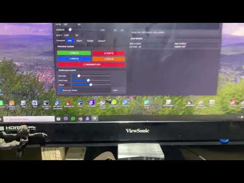
    Here is the program from my Google Drive.
    Free to download, no virus 100%.
    If your system reports something "risky" or "suspicious" - your system has been brainwashed by neoliberal zionist paranoia.

    https://drive.google.com/file/d/1yeDfNbVttf5hU3VSYBD-uRWoBWsNRt6J/view?usp=sharing


    This in the video is a very cheap "dongle" sound card from Aliexpress.
    Very modest possibilities.
    The program should be tried with better sound cards.
    This cheap sound card works quite stable up to about 12-13kHz.
    After that it doesn't work correctly anymore.
    But it is a good choice for software and hardware development because if something goes wrong;
    the white smoke will not come from your computer or more serious and more expensive piece of equipment; but from such a cheap dongle.
    There is no successful happy ending without white smoke along the way!

    ​
    ​

    Leave a comment:


  • ivconic
    replied
    Aziz you always have interesting ideas. I'm working on something, it's probably not what you want, but you might find it useful...


    ​

    Leave a comment:


  • Aziz
    replied
    Hi all,

    I didn't find my old LCR meter test board so I have built a new test board with selected and measured reference resistors (10, 100, 1k and 10k). And I have been testing some available software for sound card based LCR meters:
    - Visual Analyser 25.78 isn't working. It is stucking in the calibration mode and nothing happens. Link: https://www.sillanumsoft.org/
    - Daqarta works fine. But it is limitted to 21 kHz and 16 bits. Link: https://www.daqarta.com/dw_0o0z.htm
    - LCRMeas works but I don't know how to calibrate it exactly. The user manual isn't updated and has inconsistencies. Link: https://www.dsp4swls.de/lcrmeas/pictures.html
    - My own LCR implementation (Win32) is working like Daqarta. Without these limitations. But I have to check the calibration part. I suspect, there is a bug. And I can't check this out at the moment. I don't find the white paper for the implementation details anymore. Looks like a time consuming reverse engineering project.
    Funny part: I have added a filter part to my LCR meter. And it caused a funny and strange side effect bug, which took me a long time to find it.

    Anyway, I have my PeakTech 2170 to start with.

    All the effort is to know, what really happens to the transmitter side (TX) on really heavy mineralized ground. What are the max. limits? Can we extract more valuable infos out of the TX-side for GB and so on?

    Cheers

    Leave a comment:


  • Induction Balance Stuff - Single/Multi Frequency Response, GB, Disc, Measurements, Ideas, Fun, etc.

    Hi all,

    I'm starting a new long thread - a funny blog of my experiments, measurements, experience and findings - related all the good stuff in the thread topic.
    The goal of this effort is:
    - to have fun and entertain you
    - to improve metal detection, GB, Disc, etc.
    - to try new ideas or methods
    You are welcome to contribute to this thread.

    Before we enter the really complex stuff, I will do some basic measurements on coils, the different physical effects caused by (mineralized) ground, target and other stuff.
    I have:
    - a super-duper expensive LCR/ESR-meter (PeakTech 2170, approx. 260 bucks (€) worth)
    - a few USB-Sound cards for measurements (up to 96 kHz or 192 kHz sampling rate @24 bits resolution)
    - old Tektronix analog oscilloscope (it's still running )
    - heavy mineralized stuff (real Australian hot rocks from Brian, lots of different iron oxides (hematite, magnetite, maghemite) )
    - an empty brain (all resetted - I have forgotten everything..), a good starting point, maybe I remember something..

    Fun fact: The LCR-Meter PeakTech 2170 is absolutely useless. WTF!
    It does not really allow real-time measurements on changing physical conditions. The reading (measurement) will be freezed and any changing condition to the coil won't be measured anymore. Or it takes too much long time (long coffee break ..) until you see the very very slowly changing readout. I have to change the measurement mode or switch off and on again to make a new measurement under new conditions. That's not the definition of real-time measurement. But hey, it's a 260 bucks super-duper ground breaking thing.

    So I have to measure inductance/impedance of the coil the other way using a sound card LCR meter. This is the most cheap and convenient method and you see the instantaneous​ change of varying conditions to the coil and thus making real-time measurement possible. There are many free to use sound card LCR meter software (like Daqarta) on internet and you only need one reference resistor (10 Ohm is enough), two stereo 3.5 mm connectors, cables, a small test board. This kiss and cheap solution outperforms most of the expensive LCR/ESR meters.

    So I'll either use the available software or will use my own LCR-meter solution. And then let's look what happens to the coil under varying conditions. I'm sure, I can even measure the skin effect of the coil. It takes some time until I have prepared everything for real measurement.. stay tuned..

    Cheers
    Aziz
Working...
X