Announcement

Collapse
No announcement yet.

TF-900_TM800

Collapse
X
 
  • Filter
  • Time
  • Show
Clear All
new posts

  • Front panel is done with UV printer.
    I gave myself freedom to make funny panel setup and use that logo.

    Comment


    • PCB :

      Click image for larger version

Name:	TM800.jpg
Views:	347
Size:	835.7 KB
ID:	415053

      Comment


      • test

        Comment


        • Originally posted by ivconic View Post
          It's amazing how distracted and lost I am!


          Click image for larger version Name:	20230909_090409.jpg Views:	0 Size:	389.1 KB ID:	415044Click image for larger version Name:	20230909_090430.jpg Views:	0 Size:	203.7 KB ID:	415045
          Click image for larger version Name:	20230909_090455.jpg Views:	0 Size:	489.8 KB ID:	415046Click image for larger version Name:	20230909_090459.jpg Views:	0 Size:	267.3 KB ID:	415047
          ​​​​​
          Video is missing.

          Comment


          • As soon as I solder those connectors, of course!

            Comment


            • Originally posted by ivconic View Post

              Now after all this work and effort, I am 101% sure that I would never publish this work in public.
              But... I already promised I would... and I'm a man of my word.
              Enjoy.
              Who knows why that is good!?

              Comment


              • Comment


                • It actually works!???
                  Who would say!??


                  Of course it works!


                  I dare to say it is working slightly better than original (probably due new components).
                  There was only one mistake on pcb draw,
                  ​Berreizeta noticed it in one of the previous pages.
                  Thanks Berreizeta !!!

                  ​

                  Click image for larger version  Name:	CROSS POINT.png Views:	0 Size:	113.9 KB ID:	415085
                  ​
                  Once i spotted that post; I corrected it by cutting the trace and put the wire (simple fix).
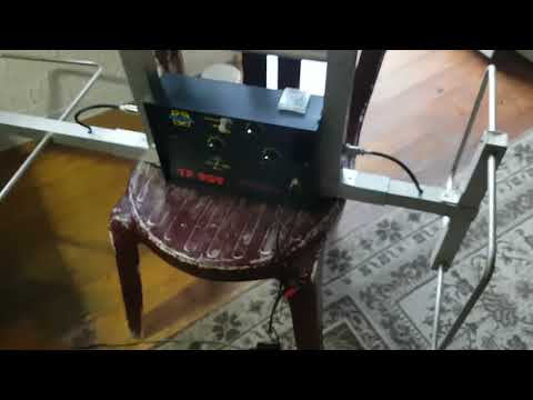
                  Now with connectors in place I see quite good behavior.
                  GEB is pretty "strong" and restrictive, so the GEB pot is approx at 1/5 on the video.
                  "Fast/Slow" autotune works by the book, excellent. "Off" (non motion) is pretty stedy for quite a while and than starts singing (normal).
                  Only problem I have right now is the headphones jack; I put wrong one and it took me 10 minutes to figure out why it has no audio in speaker!?
                  I have to replace it or omit it.
                  Also I have to finish few small mechanical details and than it is finally over!
                  It was about the time... because I completelly forgot it until today.

                  Comment


                  • Can you use a pot lid for test?
                    If it is above 1 m, the device is good (at least in the air).

                    Comment


                    • Probably some of these days.
                      I have few minor mechanical details to finish and as I mentioned; headphones jack to replace or to omit.
                      Alu pipe on video is 2cm diam and very thin walls ~1mm.
                      Just for skim testing.
                      But it looks promising.
                      This device is not finished yet.
                      It was forgoten and abandoned for several months.
                      Now I got some new enthusiasm and drive to finish it as soon as possible.
                      Once is done I will perform better tests.

                      Comment


                      • You are using circuit as on post #106 ?

                        Comment


                        • Yup.

                          Comment


                          • Originally posted by ivconic View Post
                            Probably some of these days.
                            Now I got some new enthusiasm and drive to finish it as soon as possible.
                            Once is done I will perform better tests.
                            Then you convert it to МГ-17, I can assist you

                            Comment


                            • Originally posted by pito View Post

                              Then you convert it to МГ-17, I can assist you
                              I have 4 pcbs left, so this winter we can have fun with such attempts, no problem!

                              Comment


                              • But!
                                The story is not over yet!
                                I have only two pictures of something pretty intriguing (at least for me).
                                It is "gold module" as I heard.
                                As I understand; it is addon for these detectors.
                                And that's about all I know, no more details!


                                Click image for larger version

Name:	gm1.jpg
Views:	338
Size:	115.5 KB
ID:	415117Click image for larger version

Name:	gm.jpg
Views:	323
Size:	133.6 KB
ID:	415118​​

                                Comment

                                Working...
                                X