Announcement

Collapse
No announcement yet.

Noiseless power supply for SD2200V2?

Collapse
X
 
  • Filter
  • Time
  • Show
Clear All
new posts

  • #31
    Thank you for the pictures Bill.

    If you have a Google email account, you can use picasa (http://picasa.google.com/). It's a great photo sharing service that will let you serve full size images.

    You can also email me the pics at my email, and I will gladly host them from my picasa account. I'm looking forward to seeing them blown up. Currently, the ones posted are a bit too small. It's hard to see any details.

    Comment


    • #32
      High Resolution Pics.


      TX-RX Componet Side^^^ Power Side^^^^

      This is the Battery In side ^^^^^^ I'm trying to figure out what the SOT23 chip is to the Left of the Big Cap!! Anybody have any Ideas???


      Any Body have any luck getting the "Paint" Off these boards. I tried some MEK and it worked a little after a fasion.
      What is the Stuff Anyway????

      Comment


      • #33
        Hi Bill,

        To get the paint off, either find someone who does soda blasting(like sand blasting but not as harsh) Google it!
        Or the way I do it is contact cleaner and a small flatblade screwdriver. After a while the contact cleaner makes the paint go a little bit soft and it seems to lift off a bit easier, either that or the determination goes up a gear! 
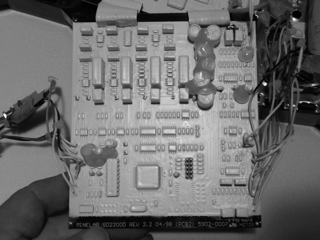
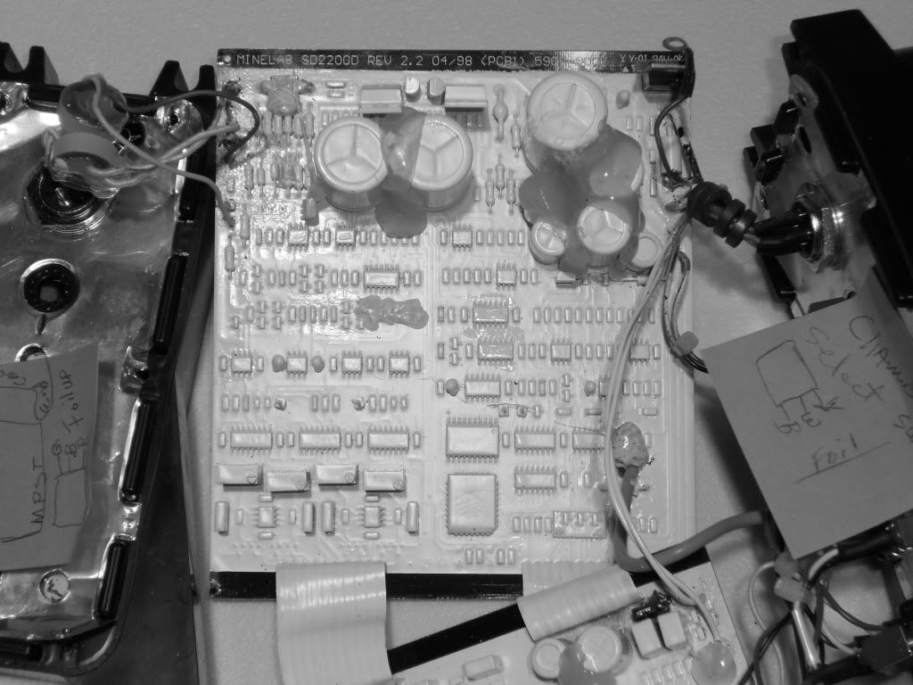
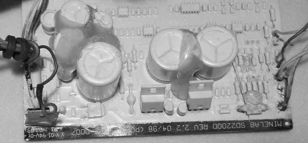
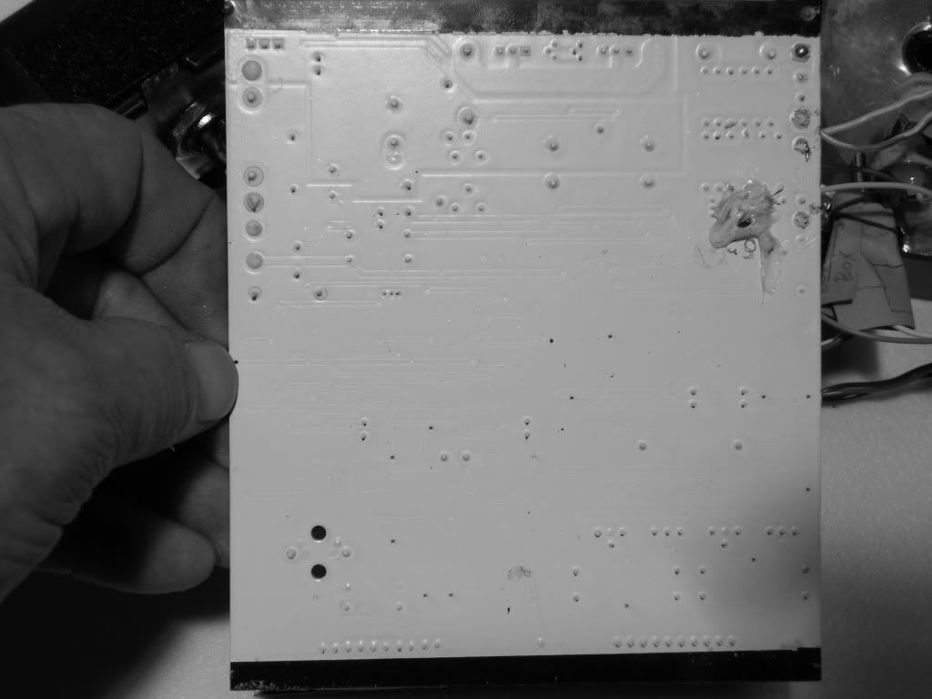
When finished, just clean up with more contact cleaner and dry. You will need to coat the boards with plasticoat or some other protective spray to keep the moisture out.

        Try and avoid paint stripper, it is bad stuff(for you) and can eat the copper from in vias and end up under your ic's. If you do use it you have to clean the board with water making sure there is enough pressure to clean under the ic's. Then blow with compressed air and dry with a hot air gun(don't get it too hot!)

        However, you might not need to scratch off much paint anyway, from the photo's a lot of the traces are identifiable, you can probably get away with just using a multimeter to test for continuity. When cleaning the tops of the components, be careful as there will be resistor markings there, make things easier if we can just read the value.

        Cheers Mick

        Comment


        • #34
          Man, I just wouldn't go where you are going with this. Too much risk. Just work on the Lipoly battery adapter idea you had at first and stop there. Look at the part I mentioned and others like it. Camcorder batteries work, but aren't as plentiful anymore and cost a lot. Drill batteries just aren't found in Home Depot or Lowes like you would think. They often cost as much as the drill did when it came with one. I would go with RC Lipoly batteries. Check them out at Hobby People or online. You can get one of these for $10-25 for >2000mA, parallel them if you want. Get one of their hobby chargers for fast charge - less than a half hour rather than overnite. The hobby chargers can run off AC or your car battery.

          Comment


          • #35
            bkline,
            I'm not going anywhere with this! Read the posts on the last page , by IBGold, Mario, Mechanic and I. WE ALL pretty much agreed that doing what Woody suggested wouldn't work in the real world, just in therory. I nor they have found any parts that have a fast enough on-off cycle to not inject noise into the RX side of the cct.

            IBGold suggested to follow his solution of an EXternal power supply Kit.

            I'm not convinced that the EX supply route will work in "REDUCING the Noise that gets Picked up in the RX CCT" by having the power Switched to a lower Voltage, taking the place of the Battery.
            Battery Vdc is linear and doesn't inject noise into the CCT. The Switching CCT in the machine is the problem and I don't know if this CCT will compensate for an External Switcher or just add the noise of the External to itself????

            These are Questions I have and need to be answered in Theroy BEFORE I Strip the onboard switching CCT and replace it with MY, or anyone elses for that matter, PipeDream!

            What you see in the High Res photos is my Solution to the URBAN Myth that the SD2200D and the SD2200V2 and the GP Etreme have the same CCT boards or are similar. The're NOT.
            This is very apparent by looking at your pics you posted and my pics and the link to Woody's pic of his SD2200D power supply end.
            at the following link;
            http://detectormods.maxforum.org/201...pgrade/#post15

            All I wanted to do is REPLACE the Weak Fet with the One Woody suggested, so I can run FROM a Battery at 7.6Vdc for 4 hrs at least. I don't like to have to keep comming back to the Rig In mountainous terrain untill it gets Dark.

            I am Still trying to ID the 2N7002 FET so I can replace it with the IR part and the Bipolar transistor ZTX688 because it controls the other half of the CCT, and I don't want to swapout the wrong one.

            The other reason for posting the pics is to see if maybe we can get a CCT Schematic Started off the old 2200/2100 ones.

            Anyone interested??????

            Sincerely
            Bill Adams

            Comment


            • #36
              Hi Bill, I think bkline was advising against removing all the white paint. Usually what happens is unintentional damage to the caps since they easily soak up whatever cleaner fluid you use.

              Anyway, take a look at the picture I uploaded. To identify "2N7000", simply follow it's gate, it's connected to a 100ohm resistor; afterward, it will eventually connect to an IC (hex4093). The drain will be connected to the annode of a diode (maybe it could be the big ugly diode seen also in the picture, to the right of no. 3? ). And the source of "2N7000" will be connected to battery ground.

              My machine uses ZVN2106, not 2N7000, and if I had to guess, it would be either of those parts I numbered as 1,2, or 3.

              I don't know if it will help much by making this part beefier. If anything, you probably want to find one with a lower Vgs to make sure the gate is fully saturated. I will have to go with the general consensus that the power cct is noisy and needs to be overhauled in these older SD models. After looking at your pictures, I'm glad to see that your board has the 27C256 eeprom since you can make this detector much more sensitive if you wanted to by playing with its contents.

              If you want to find a replacement circuit for the power section , you can always look at designs found in pcb software. Eagle comes with several designs. I use Sprint Layout 5, and it also came with several designs...all of them ready to be printed.

              Also, what is the difference between SD2200D and SD2000V2? is the SD2000D a first generation V2?
              Attached Files

              Comment


              • #37
                Correct Mario!
                Bill, you fundamentally want a better battery system that is hopefully cost effective, doesn't add noise, and allows longer use than the stock battery. My switcher suggestion would technically have noise compared the the battery but I doubt you'd see an effect from it - as these external battery kits are popular for the Minelabs. The switcher approach has the benefit of a soft-start system - but maybe that is included in your detector as it stands (I don't know). Coiltek does seem to recommend switching the detector on first, then the battery system so it makes me think most models don't have a soft start On switch.

                The RX adder to the power profile is probably minimal to the TX and control circuits. RX power sequencing is surely do-able but I'd let the manufacturers work that one.

                I would not use a LM350K as those run damn hot (waste energy). They probably have something like a 3V dropout so your battery would have to be 3V higher than desired output. The switcher runs cool to the touch, and its amazing - the noise gets smaller as the (constant) load increases in my tests. It responds fast to transient demands. I'll probably be making one of these up for myself once I get the GP working. I have some 5AH lipolys to use!

                Have you heard bad things about the Pocket Rocket and such?

                Also, changing the circuit to use a higher input voltage will likely end up in it drawing more power. You don't want higher voltage you want more AH. Better to use the lipoly battery circuit and figure how long you want it to run and buy batteries with enough AH's given the 75-80% efficiency rate of the switcher. I'd do it just for the weight aspect.

                Barry

                Comment


                • #38
                  Thanks mario.

                  bkline, I haven't heard anything one way or the other about the pocket rocket.
                  I just can't see my way to pay for a switcher cct from some one else.
                  I bought a couple of lithion bats from Woody when I had my SD modified a couple of years ago. I wasn't too impressed with what I got.

                  I decided to go on a hunt for a better system than all the others out there.
                  My final system is a unit much the same as the old Minelab battery. It has a hot molded KYDEX pouch for 2 or 3 or 4 --7.4vdc camcorder batteries in pararel, so you can use 1 to 4 and it just adds AmpHrs. It's not very elegant or pretty. I had just bought the KYDEX when I read on a post by Woody, that you could use a different input MosFet and then run the machine at a higher Vin. So I stopped building the unit to explore this Subject. I ran into a SERIOUS Lack of Info and Schematics on the SD2200V2. And so Started this thread to see what the general concensious was on the subjects that have been discussed here.

                  mario, I didn't get to your question on the Difference between the SDxxxxD and the SDxxxxV2. I don't know much about the history of the two units, but do know that the D series is the one that is Very Popular in Australia and I have been told that the V2 units are very scarce there. I don't know why.

                  Maybe mechanic or IBGold could give us some history???

                  I know that when I got the SD2200V2, in 2009, it came with a Video Tape on it's operation. Doug Stone was the trainer and he was using the SD2200D in the video. The video looked like it was an Oficial one from MineLab.

                  I am including two high res pics from my USB Microscope, on where I romoved some paint from the cct brd. I had originally thought I had Scrapped off the TRACEes, but after close inspection I id'ed the presense of a copper trace UNDER the BLACK Epoxy/Mask/Paint/????.

                  I am beginning to think that this white paint and black mask?? are just Environmental SEALS, for mainly protecting the Board from the elements. MineLab makes Military Mine Detectors and I can see them just having 10,000 boards made that would use the same layout for both types, and just substitute componets and MCU Code for each different use. AND Yes I Know its the living Pitts none the less.

                  I'm comming down with the creeping crawling lung crud so won't be posting much till I over it.

                  Mario, I'll try to get the paint off the componets you labled and get some pics of that part of the board.

                  What is the procedure for firing up the detector in the lab/house. This is just to trace and measure the voltages to the Fets you outlined. and some other points.

                  I know that Woody shows a fig 8 coil in his videos.

                  Do I need to have the DD coil attached and set to cancel? Or is that just for measuring target response?

                  Well I'm done in!
                  Bill Adams


                  Comment


                  • #39
                    HI Bill,

                    Looks like black solder mask to me. Instead of the boards being green, they are black!

                    For running the machine on the bench you need to attach a small heatsink to the fet that normally screws up to the case. Make sure it is isolated from the fet tab though otherwise you will know about it if you bump it with your hand! Also it might be an idea to use some hot melt glue to attach the heatsink to the board so the legs don't break off the fet if it gets bumped around a little while handling the boards. Do not leave the heatsink on when you go to put it back in the case!

                    Does the 2200 have cancel? You really only need to use it when your doing actual target tests. It does not matter otherwise.

                    First up it might be an idea to clean up all of the test point pins and take photos of the scope so you have a reference if at some stage something goes wrong.

                    Then scope the pins on the little fets that we are trying to work out. Don't forget to record what the scope settings are. It is a good idea to use a picture/paint editor and put what you are testing and the scope settings in each picture.

                    Can you also take a pic of the back of the coil plug so I can give you a few things to do there for some further tests, just so you know where the machine is at noise wise. Then you will have a benchmark so you will know if the machine is running better or worse if any changes are made.

                    When you are scraping the paint away, stop when the track starts to become visible. That way it will be much easier to figure out what goes where. Black traces with white background, nice.

                    Don't blow anything up now will you

                    Cheers Mick

                    Comment


                    • #40
                      One thing I haven't seen mentioned - those 2 ribbon cables connecting the two boards will not take very much flexing at all before their wires begin breaking at the pcb. I've run across them before and tried to take care but at the last, after fixing a bad coil plug on the coil cable, replacing bad parts, I found 4 opens on the ribbon wires and 2 intermittants. The paint on them makes it even more likely to fail. As you have opened up yours to photograph the boards they are at risk.
                      Any sideways motion of one board compared to the other really gets them and I think this is where I made my mistake as my pcb edges were deformed by the panel mount screws and were hard to reinsert into the extrusion slots without creating this kind of stress. Using these coarse thread metal screws here really sucks. Also the edge of the extrusion is painted/anodized so doesn't make a good connection to the panel EMI shield.
                      Is this designed better in newer models?

                      Comment


                      • #41
                        Guys, I am going to be down for a while with Bronchial Phnomia. I have also sold my $4000 Sony CamCorder and will spend tommorow packing and shipping it. Then in 3-5 days I can get my money from paypal. I will try to get the Bench cleared off so I can get the 2200V2 on it and the O-Scope set up. I have HD Video Capabilities and 14MgPixel camera for High Resolution Pics like before.

                        bkline, as far as the cables go, I'm thinking of using some old PC Ribbon Cable and soldering it to the place where the crap Cable is now. It is VERY Flexiable and won't break. I know we used to fold and bend it over on itself and it was carrying signals from the harddrives and other equipment. The only thing I see is the Spacing of the strands on it and the spacing of the pins on the boards.
                        What EMI shielding are you talking about?

                        Yea, mechanic thats what I thought it was (solder mask), but had NEVER seen it that color before. Don't know what significance that Black has to minelab maybe it was to differencate the Newer Batch board runs from former runs. Or maybe the Gold Detecor boards from the Military ones???? An thanks for the pointer on bench tests.

                        Sorry I didn't get the paint off the numbered componets and pics taken. Will try again tommorow. I have to call and tell a friend of mine that I can't speak to his group about metaldetectors on Thur(29). AND it's a 2.5hr drive one way for me to go there. He had me schedualed for 15mins, with questions and I wasn't very thrilled on the SHORT Presintation anyway. 15 mins isn't enough time to explain about VLF's, PI's, and Target Size in relation to Coil Size, in relation to Depth, and relation to ground minerals. AND THEN have a question and Answer period. I see at least 45mins to 1 hr on the above and then a half hour Q&A sesion. This would allow for showing of Bench Testing and Ore Sampling techniques.

                        Sincerely
                        Bill Adams

                        Comment


                        • #42
                          I haven't come across a thick enough ribbon cable in the stores yet.
                          Molex makes em but I'm not about to order 100'.
                          May be just fine with separate wire X 10.

                          Comment


                          • #43
                            Barry,
                            What about using a piece of floppy or Hard drive cable. They're not as stiff as the current cable and may be a little more forgiving as far as flexing. Plenty of wires on each. Pull off what you need.
                            Just a thought, or am I way off base here . . . . . .

                            Jonn

                            Comment


                            • #44
                              I will be using twinlead wires taken from power adapters I characterize at work. The spacing is perfect and the wires are beefy - just right for the holes. It was not easy taking the old ribbons out. Best to just cut them with side cutters about 1/4" from the pcb first. As it was, I needed the microscope at work to do it right. Still I may have damaged one hole's through-hole plating. Won't know til I get it all back together. The IDE or floppy cables can work but will not be robust. This twinlead I'm using has like 10 times the wire as those.

                              Comment


                              • #45
                                bkline, what is the difference between the floppy/hdd cable an the stock item minelab puts on. I can't see any difference in the amount of copper in the two. I think that minelab just used that type of cable because they got a GOOD Deal on it and it did the job adequitley. I think that is like the Battery system they used. At the time that was the Best Off The Shelf system to use. It had Nothing to do with "WAS It the Best".

                                The only way to say on any of this is to Measure the Voltage and Amps across each of the connecting wires and them compute the 120% to 130% overage in cicular mils to carry that load.
                                I'm not trying to nitpick you, I just don't want any newcommers thinking that they have to run Big Cable between the two boards, when Mollux will suffice nicely.

                                BUT I could be wrong also.
                                Sincerely
                                Bill Adams
                                ps starting to feel better, hope to have the Fets Washed Off and pics soon.

                                Comment

                                Working...
                                X