Announcement

Collapse
No announcement yet.

LOOKING FOR GOLDSCAN 4 Schematic.

Collapse
X
 
  • Filter
  • Time
  • Show
Clear All
new posts

  • ivconic
    replied
    Originally posted by Carl-NC View Post
    The damping affects how early you can sample. Normally we talk about critical damping but in reality you can usually be somewhat under or over damped and everything still works, as long as the preamp is out of saturation at the start of the sample. If so, then depth doesn't change with damping and optimizing the damping won't solve your depth problem.
    Clearly.
    I didn't even expect that proper damping will solve the "depth" problem.
    I just wanted to check how much difference there is between the provisional value of 470R that I randomly chose (because is 5W) and the real value that I will get with the "jig".
    As time goes on, and as my experiments pile up; I start to suspect more and more that there is something else wrong with the pcb design.
    I have already found 5-6 errors which I corrected and posted here on one of the pages.
    But it is possible that there is another one. I don't know who drew it, but it definitely raises suspicions.
    I hate wasting time and looking further for mistakes. I have another pcb design that is (supposedly) 101% verified.
    And I plan to make a detector on that pcb.
    But even this pcb with errors is good enough for exercises and experiments.
    All the time the serial 2R2 is on the pcb. Someone suggested that I remove it, but I don't think it will significantly affect the problem.
    Someone else made a comment about the J112 and how that fet "does not work good".
    And then someone else says their detector works great with the BF245.
    I'm almost certain that has nothing to do with the problem. The J112 will work perfectly fine there as well as the J113.
    It's just... everything mentioned so far doesn't make sense. And it's not true reason for the problem.
    Barracuda has a range on the same targets 5 times even more!
    Of course, with the Barracuda there are no two channels and no channel mixing due to GEB.
    And this GS4 pcb, in "Off" mode, has noticeably better "depths"... but not half as much as the Barracuda.
    It's rude to say it... but this whole thing about the GS4 is one big horseschmitt!
    But I'm satisfied, I had very extensive exercises, experiments and I "returned" to the topic a lot.
    ...
    Carl you didn't suggest damper values ​​for the given coils?
    Nor did you choose the moment on the video that you think is the best damping?
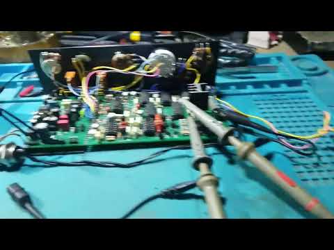
    ​

    Leave a comment:


  • Carl-NC
    replied
    The damping affects how early you can sample. Normally we talk about critical damping but in reality you can usually be somewhat under or over damped and everything still works, as long as the preamp is out of saturation at the start of the sample. If so, then depth doesn't change with damping and optimizing the damping won't solve your depth problem.

    Leave a comment:


  • ivconic
    replied
    The "flick" in the video is when the damn fridge at the other end of the room turned on... probably powered by the same phase...

    Leave a comment:


  • ivconic
    replied
    Ok, after a short break, relaxing on the field with Deus, a couple of nice finds... the weather turned bad again, cold, strong wind, occasional rain... time for the workshop!
    One whole day my attention was diverted to the other side, it was all the fault of some pathetic french maricon... but that is not the topic for this forum.
    Ok, I managed to somehow "wind" the spiral coil!
    Oh what a pain!
    The combination of "super glue" and two-component epoxy... in the end it worked, but it turned out very ugly from an aesthetic point of view!
    The first tests did not show any improvement compared to ordinary coils.
    Ok, I get it.
    The spiral coil will allow a shorter delay and better sensitivity on very small targets.
    Currently, the minimum delay is still ~10uS, I changed PPS back from 1000 to 500Hz as well.
    In the picture you can see both coils and their specs.
    In both cases, with both coils; the "depths" of the detection are ... to put it mildly... miserable!
    No matter what I try, no matter how I adjust...
    GEB works ok.
    "Disc"... in "All" mode generally sees better conductors better.
    In "Sel1" mode it practically detects nothing!?
    In "Sel2" mode, it sees better small objects and worse conductors, while better conductors and any iron... it DOESN'T SEE at all! (interesting!)
    So far the damper resistor is 470R/5W all the time.
    ...
    Then I removed the 470R damping resistor and put a "damping jig" in its place. And observed the situation on the oscilloscope.
    I found certain damper values, for each coil separately, with which; it seems to me:
    that the detector works ok, although this did not affect the improvement of the "depths" on the mentioned targets.
    Ok, now you have all the data.
    I'd love to hear opinions.
    So far, there has been too much theorizing about damping and related topics on many topics on the forum.
    I read everything. And I have my own opinion and attitude. Which I won't reveal for now.
    Watch the video and suggest a moment in the video, when, according to you; best dumping achieved.
    This is also a good rehearsal and test for too much theorizing and playing games in simulators.
    Come on... experts... let me see/hear you!
    And at the same time, let's check your "mathematics" about the damping value!


    ​Click image for larger version  Name:	Spiralna i Omega sondand.jpg Views:	0 Size:	759.6 KB ID:	421812

    ​

    Leave a comment:


  • ivconic
    replied
    It was Carl's idea.
    Use 10k resistors, one side to the gate on fets and other sides from resistors solder together.

    Leave a comment:


  • kadir6141
    replied
    Originally posted by ivconic View Post
    @Carl:

    Click image for larger version  Name:	Q4.jpg Views:	178 Size:	506.3 KB ID:	421062Click image for larger version  Name:	Q4_Q5.jpg Views:	176 Size:	846.6 KB ID:	421063Click image for larger version  Name:	Q4_Q6.jpg Views:	175 Size:	767.1 KB ID:	421064Click image for larger version  Name:	Q4_Q6_Q5.jpg Views:	178 Size:	880.1 KB ID:	421065
    Click image for larger version  Name:	Q4_Q7.jpg Views:	174 Size:	758.8 KB ID:	421066Click image for larger version  Name:	Q4_Q8.jpg Views:	175 Size:	735.7 KB ID:	421067Click image for larger version  Name:	Q4_Q8_Q6.jpg Views:	176 Size:	752.1 KB ID:	421068Click image for larger version  Name:	Q4_Q8_Q7.jpg Views:	178 Size:	749.7 KB ID:	421069​​
    Hello Mr. Ivconic, how can you see all the timings at the same time with an oscilloscope?

    Leave a comment:


  • GeoMax
    replied
    The LT1114 in the PDIP version (Truehole) is obsolete and is no longer recommended for new designs. However, the SMD version of the LT1114 will continue to be produced.

    Leave a comment:


  • eduardo1979
    replied
    Originally posted by Emersonpaz View Post

    LT1114 seems out of stock is there any replacement?
    At mouser elecinics they are available.

    Leave a comment:


  • Emersonpaz
    replied
    Originally posted by eduardo1979 View Post

    Why don't you make the GS-5?
    In my opinion it is a better detector than the GS-4.
    In the past I made a LITE version of GS-5 and it worked very well.
    My LITE version has the identical time base as TDI SL.
    The VCO is very nice, because it has a CD4046.​

    https://youtube.com/shorts/2tXTbySBUD4
    LT1114 seems out of stock is there any replacement?

    Leave a comment:


  • ivconic
    replied

    Leave a comment:


  • Jose
    replied
    General tech discussions on all types of metal detectors: VLF, 2-box, BFO, off-resonance, PLL, etc. Questions, ideas, and anything else that moves you.

    Leave a comment:


  • pito
    replied
    Voltage on pin 5 ?, how much is changing voltage on pin 6 when turning potentiometer 50k ?

    Leave a comment:


  • kadir6141
    replied
    Originally posted by pito View Post
    it is changing on pin #7 ?
    No

    Leave a comment:


  • pito
    replied
    it is changing on pin #7 ?

    Leave a comment:


  • kadir6141
    replied
    Originally posted by pito View Post
    Click image for larger version

Name:	image.png
Views:	622
Size:	170.8 KB
ID:	421520
    To see the voltage changes on pin no. 8, the voltage on pin no. 10 must change slightly below or above the voltage on pin no. 9, in your case you won't see this because the voltage on pin no. 10 is lower than 0.06 mV, check the circuit , set pin #10 to -15mV and adjust the voltage to "0V" with a 50k potentiometer, you should observe the voltage change on pin #8.
    Hi. Mr pito The voltage on pin 8 does not change constantly. -4.20v to -4.17v

    Leave a comment:

Working...
X
