If this is your first visit, be sure to
check out the FAQ by clicking the
link above. You may have to register
before you can post: click the register link above to proceed. To start viewing messages,
select the forum that you want to visit from the selection below.
Alex's original scheme does not include the GND connection of the fet.
Two 470K resistors were added on both channels.
A 220K resistor was replaced by 22K.
Use the scheme indicated below, it is the one that works on my GS4.
The data sheet says
"J111 / J112 / J113 / MMBFJ111 / MMBFJ112 / MMBFJ113N-Channel SwitchFeatures• This device is designed for low level analog switching, sample and hold circuits and chopper stabilized amplifiers.• Sourced from process 51• Source & Drain are interchangeable"
Greetings and regards jose.
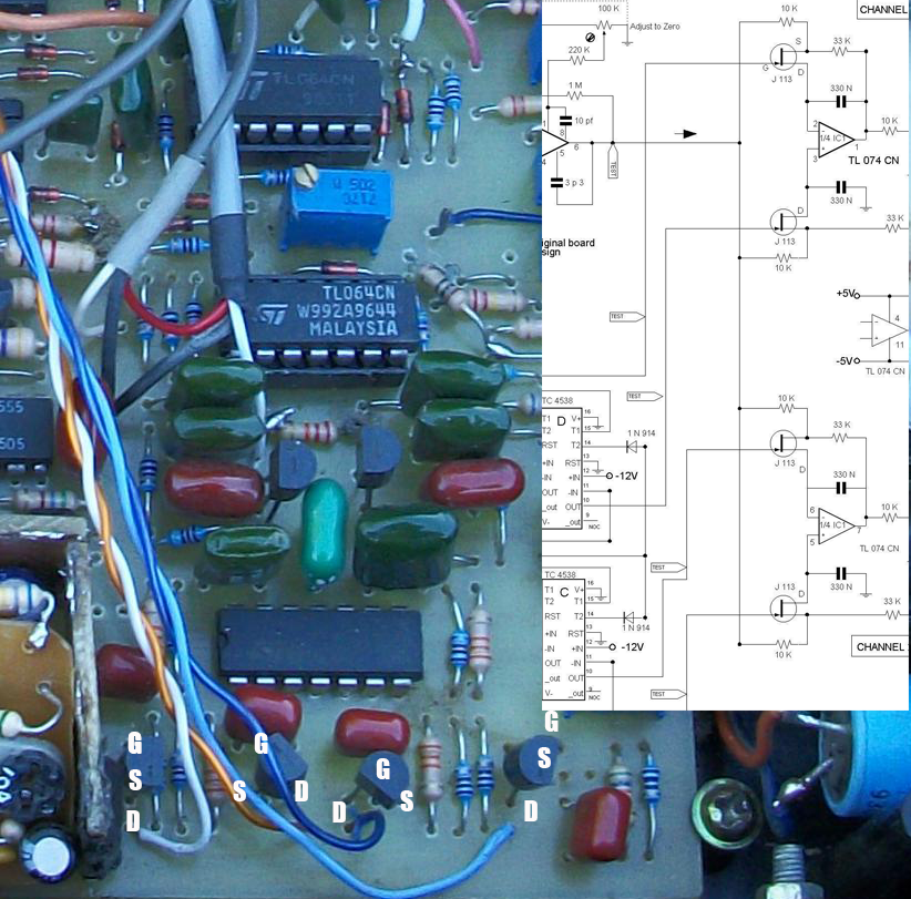
I suspect your goldscan 4 in this photo.
between the scheme here and your goldscan pcb array j113 s different connection.
Drain pins on the diagram are connected to the integrated. but drain on the pcb is shelf. is the correct connection?
Your attachment seems to be missing, but Source & Drain are interchangeable on J113
For the case of Q9 and Q10, the "S" terminal is connected to ground or GND. The attached diagram is correct, although there could be some error.[ATTACH]44349[/ATTACH]
Greetings and regards jose.
I suspect your goldscan 4 in this photo.
between the scheme here and your goldscan pcb array j113 s different connection.
Drain pins on the diagram are connected to the integrated. but drain on the pcb is shelf. is the correct connection?
I think it should, measure the current consumption, which should be 200 to 250 mA.
The voltage should not be too high 15 or 16 volts, with those values and a good heat sink in the regulator, should not have problems. The scheme indicates 3.5 ohms for the coil, see the first page, scheme published by KT315 https://www.geotech1.com/forums/atta...6&d=1123969824
I think it should be because I use a very thick wire for the coil .. I get 1oh the wire is thick 18 .. what wire is the ideal? ... Thank you for any information
Goldscan is very very tricky to get properly working.
I would strongly suggest looking into easier project like Minipulse and Barracuda which do have complete "final schematic"
Bonsoir Jose excuse me for my language;
i hope you send me the schematic final for this machine ,with allimentation schematic
it's my first experience , thank you


Leave a comment: