Ok, 10k gives me 890-1300 Hz !!! Wow!
Behavior of the detector hasn't significantly changed... except this; with loud audio detection overall power consumption now is .... 150mA !?????? WTF???
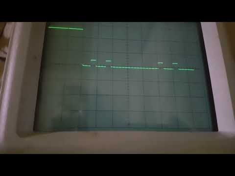
Carl you gonna love this; yes you are right, all 5 pulses can be scoped at the same time!
Here is the Delay behavior and timings:
Announcement
Collapse
No announcement yet.
LOOKING FOR GOLDSCAN 4 Schematic.
Collapse
X
-
@Carl,
R8 = 47k, 10k instead will allow adjustments up to 1000pps...
This is the first "tweak" to do and see the changes in behavior... if any.
This will be the "second phase" of the job where things will go very slowly...
To avoid white smoke!
Leave a comment:
-
I have good results on IB VLF, just out of curiosity, I'm thinking about trying PI.
I hesitate to do so because the PI detectors I've seen, for coins have a 50% shorter range.
Leave a comment:
-
It's obvious you're new to this stuff...
You repeated some mistakes on your Barracuda rewrite too.
But for your sake, for your true learning and advancement; it is best not to tell you anything; but you to see for yourself in your work what will work for you and what will not.
You were in a hurry, you didn't want to listen.
The basic advice and the only one I will give you; FIRST DO the detector in basic form, as someone has already done it and it worked well for him.
And only then, when it works well for you too, and you become familiar with all aspects of work;
only then can you give yourself the freedom to "butcher" and "tailor" the project as you think would be good.
Otherwise, if you immediately start building, for example, a Barracuda according to the "butchered" schematic that you published earlier; it won't work for you at all.
Feel free to take my word for it.
And don't misunderstand these tips of mine. I have been making detectors since the early 90's. And as you can see; I made the GS4 in its original form first of all.
In order to get to know all aspects of the operation of that detector live.
And only when I do it all the way; I will start with tweaks, but not all at once but one by one, after each tweak there will be a period of testing and detailed checks.
I planned not to write you this.
But I can see even now that you will have a lot of problems and that it will not work for you.
It is better to listen to the advice of an elder.
Leave a comment:
-
The reduced range is due to mixing two channels. = instead of mixing we can calculate the magnitude and phase using stm32
Leave a comment:
-
Circuit Modification First Step;
blue line = power modification
red line = can be replaced with stm32f103,
Second step;
green line = final modification
Leave a comment:
-
Of course, that's a good way. I did the first PI in 1992. It was a kit from the Austrian Conrad catalog.
Times were much better for the hobby back then.
There were not many detectors and detectorists and the sites were untouched.
I've had a lot of great finds with that simple PI!
But I dug for all the signals.
The coil was 20cm, so it was not very deep.
Come to think of it... even today if I were to dig for all the signals; I would probably have more good finds!
And that's the background of this idea around the GS4.
That PI from the 90's was "slow" and didn't see large coins very well let alone smaller ones.
I will try to tweak the GS4 mostly relying on Carl's suggestions and help.
And then I'll dig with it on most signals. It's time to find many good finds again.
And all these other VLF I/B toys have finished their story... at least in my sites.
Leave a comment:
-
I want to practice on simple one as barracuda, then on more complex. Waiting for P MOSFET.
Leave a comment:
-
For more serious experiments; first it is necessary to transfer the schematic to editable form.
I respected the numbering of the components as in Alex's schematic so that there would be no confusion.
Like always Schematic is done in : https://www.expresspcb.com/
Bellow is packed editable schematic file...
Attached Files
Leave a comment:
-
Place a 1K trim pot between pins 14 and 15 on the 4053 with the wiper going to the junction of C6 and R32. Use a magnet to adjust the ef null.Originally posted by pito View PostI think the voltage at the end of the swing is maximum it is mainly caused by the change of direction of movement, the coil sees the earth's magnetic field +65 μT then - 65 μT ...
Now I see that U2 is just preparing the signal for processing and changes from coin will be visible at the output of U4
Leave a comment:
-
My preference is to always use antiparallel diodes. One to clamp the flyback and the other to clamp the -14V. You can lower R27 to improve thermal noise but often I leave it a high value (even several kΩ) as I find that EMI is usually higher than thermal noise. A higher value for R27 also makes the diode clamp much faster which lets you sample earlier. It's one of those things to play with.Originally posted by ivconic View PostI think I understood what you wrote.
Yes, the R27...someone suggested earlier, and I agree, that it's better to put a 1K there.
And if I put anti-parallel diodes, then the value of R27 could be slightly lower.
Your opinion? And the difference in two diodes in the same direction and two antiparallel ones?
Is it related to the fact that the "ground" is at a potential of 14.4v?
- Likes 1
Leave a comment:
-
I think the voltage at the end of the swing is maximum it is mainly caused by the change of direction of movement, the coil sees the earth's magnetic field +65 μT then - 65 μT ...
Now I see that U2 is just preparing the signal for processing and changes from coin will be visible at the output of U4
- Likes 1
Leave a comment:
-
I think I understood what you wrote.Originally posted by Carl-NC View Post
You can completely omit the 2R2 and make a 0-ohm coil if you like. The purpose of making the coil non-zero ohms is to somewhat flat-top the current pulse, which reduces the target reverse eddies during TX turn-on. This is especially helpful with high conductors. See this thread, especially posts 11 & 12. Also, the 2R2 doesn't contribute noise because it is removed from the RX path. Even coil resistance doesn't hurt noise, as R27 dominates the RX noise.
Yes, the R27...someone suggested earlier, and I agree, that it's better to put a 1K there.
And if I put anti-parallel diodes, then the value of R27 could be slightly lower.
Your opinion? And the difference in two diodes in the same direction and two antiparallel ones?
Is it related to the fact that the "ground" is at a potential of 14.4v?
Leave a comment:
-
You can completely omit the 2R2 and make a 0-ohm coil if you like. The purpose of making the coil non-zero ohms is to somewhat flat-top the current pulse, which reduces the target reverse eddies during TX turn-on. This is especially helpful with high conductors. See this thread, especially posts 11 & 12. Also, the 2R2 doesn't contribute noise because it is removed from the RX path. Even coil resistance doesn't hurt noise, as R27 dominates the RX noise.Originally posted by ivconic View Post
First thing I do now is adding a heatsink, also replacing those 2 parallel 1k damper with one 470 / 5W (noticed those 2 get hot in time, 470 one is first that came handy), and 2R2 with 5W one too.
Now, I understand the role of 2R2, more like a "fuse" and to add safety resistance to coil... but from the photos of the original GS4 I see Eric put "inductive" resistor in ceramic case???
That's strange to me, because I learned long time ago to avoid "inductive" (wire) resistors on such places.
Also 2R2 could be omitted; providing that coil resistance is high enough. Speaking this in a sense of the noise reduction. But for now I'll keep it, S/N issues will come later, probably when everything else is done fine.
Leave a comment:
-
If the Earth field is exactly uniform, and you are able to keep the coil exactly flat and at a constant height, then yes, the induced voltage should be zero. But things are not so perfect, and there is a slowly changing induced voltage, with most of it being at the ends of the sweep where people have a tendency to lift the coil slightly. Between each pair of TGT and TGT-EFE samples there is very little change in the induced EFE voltage (even at the sweep ends) so the 2 samples are close to equal (almost DC), and subtracting them will mostly cancel the EFE.Originally posted by pito View PostDuring that meter of movement, the RX has sampled 500 times so each sample span sees what looks like a DC offset. = sample every 2 mm , that is good but most of the time EFE is 0V so DC offset is not precise. ?
EFE is only noticeable in a PI detector because it often has a lot of gain. If you disable EFE and very carefully sweep the coil, you might find it's not too bad. Until you get in an area with magnetic rocks.
- Likes 1
Leave a comment:
Leave a comment: