Announcement

Collapse
No announcement yet.

Arduino Nano PI Main Discussion

Collapse
X
 
  • Filter
  • Time
  • Show
Clear All
new posts

  • Qiaozhi
    replied
    Originally posted by Agme View Post
    Advise needed:
    1)I would like to make a new coil. I was going to buy some new wire, but I got overwhelmed with all the opinions of the forum. Would yall recommend a wire size and insulation. What I have concluded is that Teflon insulation is a favorite (I think), but actual wire size is all over the place. And 3DSS coils seem to be a favorite over the Fast coil documentation.
    2) I would like to build a VLF next, could you recommend a project to try. I saw the IDX pro is available from DIY detector and I not sure I want to attempt making PCBs yet.

    Thanks for the help.
    Firstly ... well done on a successful build, and thank you for reporting back to the forum on the results.

    You don't need to be obsessed with making a fast coil for the ANPI as it's designed for metal detecting on the beach, not for gold nugget detecting. A simple mono coil is more than adequate, and Teflon insulation would be good. You can use the Coil Calculator at the top of the Coils forum to estimate the correct number of turns for a specific wire diameter.
    If you do want to reduce the sampling delay then have a look at ->

    The "Investigation of UXO Paper.pdf" includes a modification to the transmitter circuit which turns it from passive to active switch-off. This reduced the sample delay of 24us to 17us (out of saturation at 15us) for the sample test coil.
    I have made good coils with 0.56mm, 0.63mm, and 0.71mm copper enameled wire, and also with simple hookup wire, so it's not really that critical.
    Make sure that you adjust the damping resistor accurately to provide critical damping.

    Regarding a VLF detector project ... TGSL or IDX Pro are probably your best options.

    Leave a comment:


  • gallico58
    replied
    Hi, I have successfully built arduino nano pulse.
    if possible I wanted some advice, the damping resistance better directed in the coil or better on the circuit, on the base?
    does the rg58 cable affect a lot in both cases?
    sorry english translated Thanks!

    Leave a comment:


  • Agme
    replied
    My Nano PI Build Experience

    Click image for larger version

Name:	Board_Front.jpg
Views:	1
Size:	101.8 KB
ID:	361780Click image for larger version

Name:	Board_Back.jpg
Views:	1
Size:	106.6 KB
ID:	361781Click image for larger version

Name:	Coil.jpg
Views:	1
Size:	72.7 KB
ID:	361782Click image for larger version

Name:	Scope_wo_shielding1.png
Views:	1
Size:	29.1 KB
ID:	361783Click image for larger version

Name:	Scope_w_sheilding1.png
Views:	1
Size:	25.1 KB
ID:	361784
    I am ~90% finished with the Nano Pi Detector and was just going to share the things I learned.
    My Background:
    I am not a dirt fisherman. I have a friend who is obsessed with the sport, so I have been a few times. However, I was intrigued on how they work. I was occasionally looking for information on how they work when I ran across Inside the Metal Detector and Nano PI books. I bought both and read them then found this forum and I decided to build the Nano PI. I was already familiar with Arduino so I figured it was an easy place to start. I have some soldering experience (perf boards, headers, etc.) but I have never populated a PCB.
    Components/BOM:
    I tried to buy everything from digikey, but some of them were out of stock or were not exactly the same description as the book. So I decided to use the BOM provided by dingbatca from Tayda. I have never used them before but they were cheap, looked to be pretty good quality, and the datasheets were easy to find. The shipping was fast and I will use them again.

    I made a few changes to the BOM or where I found the other parts:
    2-pin term 4 A-804
    female 2 pin 4 A-826
    3-pin term 3 A-805
    Female 3pin 3 A-827
    Crimps 18 A-837
    Headphone Socket 1 A-3575
    Rubber Boot for switches 2 A-5248
    15 pin Socket for Arduino 2 A-1669
    5 PINS FEMALE CIRCULAR CONNECTOR 12MM GX12 1 A-5579
    5 PINS MALE CIRCULAR CONNECTOR 12MM GX12 1 A-5573
    I added an additional 10K pot for the Coil testing setup.

    Amazon
    Arduino Nano Elegoo (I had to download the CH340 driver from Elegoo but worked fine)

    Digikey
    3R3 (2W) R3 ‎RSB-3.3RCT-ND (I had a hard time finding a 2W 1% this is a 3W)
    Coax C1188-50-ND (I also had a hard time finding this I ended up buying a spool. I hope I use it somewhere)
    Gland Strain Relief PMS12BK080-ND (sized for the coax)

    DIYDetector
    I bought the PCB board thru DIY detector. I chose the ?snail mail? option and it took exactly 2weeks to get to the US. Boards arrived in good condition and worked good.

    Coil stuff
    Wire: I miss read the book "1mm thickness, with insulation" I thought this ment 1mm wire (18AWG) with insulation and I had some 18 AWG hookup wire so I decided to use it. (.110" OD (2.794 mm))oops.
    I had some spiral wrap, material unknown.
    I had some ducting foil tape for shielding (3M 3340 foil tape) A mistake I think.

    Build:
    I followed the book instructions, and everything went smoothly. I found Surfdetector's YouTube videos extremely helpful.
    I started building the coil and noticed it didn't really look like the other ones on the forum/book. That's when I realize the wire I was using was big I didn't want to buy new wire so I just finished it / re calculated what it would take with this diameter and ended up with the following:

    9" ID/ 26 turns (18AWG-.11" OD) /.8 Ohms/300uH
    I put way too much overlap on the foil tape. There was a lot on there.
    Rd = 360 Ohm

    Coil Issues:
    I realized while testing the coil was not very fast. The response was ~100us. I cut the shielding off of the coil and it was a lot better but had a lot of noise. I think I put way too much shielding material on the coil and it was thick, so it was doing weird stuff to the coil. Attached are scope pictures of both (before and after). I didn't retest the dampening resistor so it may be able to be optimized from what its at now.
    It seems to be working pretty good but there is a lot of noise. I ordered some proper shielding tape and I am looking forward to finishing it.

    Advise needed:
    1)I would like to make a new coil. I was going to buy some new wire, but I got overwhelmed with all the opinions of the forum. Would yall recommend a wire size and insulation. What I have concluded is that Teflon insulation is a favorite (I think), but actual wire size is all over the place. And 3DSS coils seem to be a favorite over the Fast coil documentation.
    2) I would like to build a VLF next, could you recommend a project to try. I saw the IDX pro is available from DIY detector and I not sure I want to attempt making PCBs yet.

    Thanks for the help.

    Leave a comment:


  • MartyJ1963
    replied
    Great stuff Olly! Thanks for posting. Mine are nearly boxed up so I'll hopefully be taking them out soon to test. Regards, Marty.

    Leave a comment:


  • Olly
    replied
    Originally posted by Qiaozhi View Post
    Glad to hear you had an enjoyable time with your two ANPIs.
    If you change the txPeriod on line 29 in the Arduino sketch and re-flash one of the detectors, then the slight different in TX pulse rate should allow them to operate closer together.
    Cool thanks, I'll give that a try.

    Leave a comment:


  • Qiaozhi
    replied
    Originally posted by Olly View Post
    Just back from Jersey, both detectors worked very well in the wet sand but mostly found a lot of junk on the beach I'm afraid. Lots of pull tabs, bottle tops and old cans. They do find very deep though and my wife found an old Brittania Farthing in some concretion, it's not in very good condition but seems to be from around late 1700's to early 1800's so very happy with that.

    I did find some odd interference between the two detectors though and when they are within around 20 yards of each other they both beep intermittently. No problem once we kept some space between us though.
    Glad to hear you had an enjoyable time with your two ANPIs.
    If you change the txPeriod on line 29 in the Arduino sketch and re-flash one of the detectors, then the slight different in TX pulse rate should allow them to operate closer together.

    Leave a comment:


  • Olly
    replied
    Originally posted by MartyJ1963 View Post
    Great job Olly! I bet your wife is well pleased with the matching pair of pro-looking detectors! Don't forget to post the results of your finds in Jersey,,,Enjoy your Hols! Regards, Marty.
    Just back from Jersey, both detectors worked very well in the wet sand but mostly found a lot of junk on the beach I'm afraid. Lots of pull tabs, bottle tops and old cans. They do find very deep though and my wife found an old Brittania Farthing in some concretion, it's not in very good condition but seems to be from around late 1700's to early 1800's so very happy with that.

    I did find some odd interference between the two detectors though and when they are within around 20 yards of each other they both beep intermittently. No problem once we kept some space between us though.

    Leave a comment:


  • Qiaozhi
    replied
    Originally posted by Agme View Post
    Thank you. I did look at that BOM and it was very helpful, but they didn't have Rd part # (for obvious reasons). They specified some 100V caps and some 16V, I was just a little confused about what they needed to be. Sorry if these are basic electrical questions I am learning (slowly).

    Thanks
    You just need to specify the capacitor voltages to be higher than what they will be subjected to in the circuit. For the Arduino Nano PI none of the capacitors will be exposed to more than 16V. If the component has a rating higher than 16V, then it will obviously also be OK. The next important thing to check is the pin spacings, and these are listed in Appendix A.

    Leave a comment:


  • Agme
    replied
    Thank you. I did look at that BOM and it was very helpful, but they didn't have Rd part # (for obvious reasons). They specified some 100V caps and some 16V, I was just a little confused about what they needed to be. Sorry if these are basic electrical questions I am learning (slowly).

    Thanks

    Leave a comment:


  • Qiaozhi
    replied
    Originally posted by Agme View Post
    I am new to DIY Detectors and have a quick question about the BOM components.
    What should the capacitors voltage and tolerance be?
    What wattage rating should the Dampening Resistor be?

    Thanks
    Have a look at post #243 where dingbatca posted a BOM with Tayda part numbers. This should provide some useful information.

    I always use 1% tolerance resistors. Capacitors generally have a much wider tolerance, such as +/- 10%. Nothing is really critical in this design, and some people even build their projects from parts rescued from scrap boards. I would use a 2W component for the damping resistor.

    Leave a comment:


  • Agme
    replied
    I am new to DIY Detectors and have a quick question about the BOM components.
    What should the capacitors voltage and tolerance be?
    What wattage rating should the Dampening Resistor be?

    Thanks

    Leave a comment:


  • MartinB
    replied
    Originally posted by 6666 View Post
    Looks good, this write up points out a few issues
    https://www.tomshardware.com/reviews...rp2040-connect
    Too many issues to be resolved, and expensive!

    Leave a comment:


  • dbanner
    replied
    You could utter the words "beach mode" through a Bluetooth headset and presto!

    Our friends in eastern Europe might say " bittch mod" , which might cause a different effect, now all targets become rejected!

    Leave a comment:


  • 6666
    replied
    Originally posted by dbanner View Post
    Arduino nano RP2040 same form factor as the nano but a whole lot more. Maybe this can open more possibilities for development.

    Looks good, this write up points out a few issues

    Leave a comment:


  • dbanner
    replied
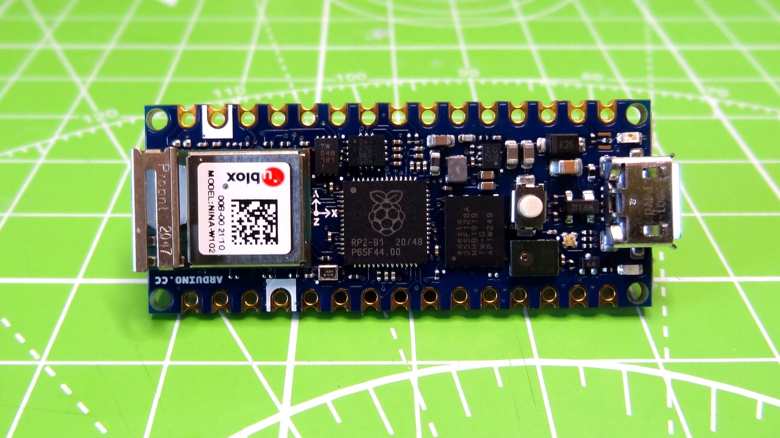
    Arduino nano RP2040 same form factor as the nano but a whole lot more. Maybe this can open more possibilities for development.

    Leave a comment:

Working...
X