Announcement

Collapse
No announcement yet.

Announcement

Collapse
No announcement yet.

Arduino Nano PI Main Discussion

Collapse
X
 
  • Filter
  • Time
  • Show
Clear All
new posts

  • Lukelearning
    replied
    I did that but it started smoking straight away!

    I have 3s Li-ion NCR18650B for the power. The voltage coming from them is 12.34V do you think this is too much for the nano to handle?

    Like I said it was working OK before but maybe I've charged them and that extra voltage has pushed it over the edge?

    Leave a comment:


  • Claes
    replied
    Tack så hemskt mycket Qiaozi !!

    Leave a comment:


  • Qiaozhi
    replied
    Originally posted by Lukelearning View Post
    Hi guys

    I had the project working fine and was about to begin assembly when I started having issues with my nanos and the power that's burned out a couple of them out. Hoping someone can help before I kill my last one!

    The first nano just seemed to go unresponsive
    The second nano 5v pin measured about 7.5v
    The third nano from a different manufacturer had a VIN pin measured 12.5v and the 5v pin about 9v before burning out.

    i first thought it was just a dodgy batch but seems unlikely now.

    If helpful this is my third and last spare nano I have:
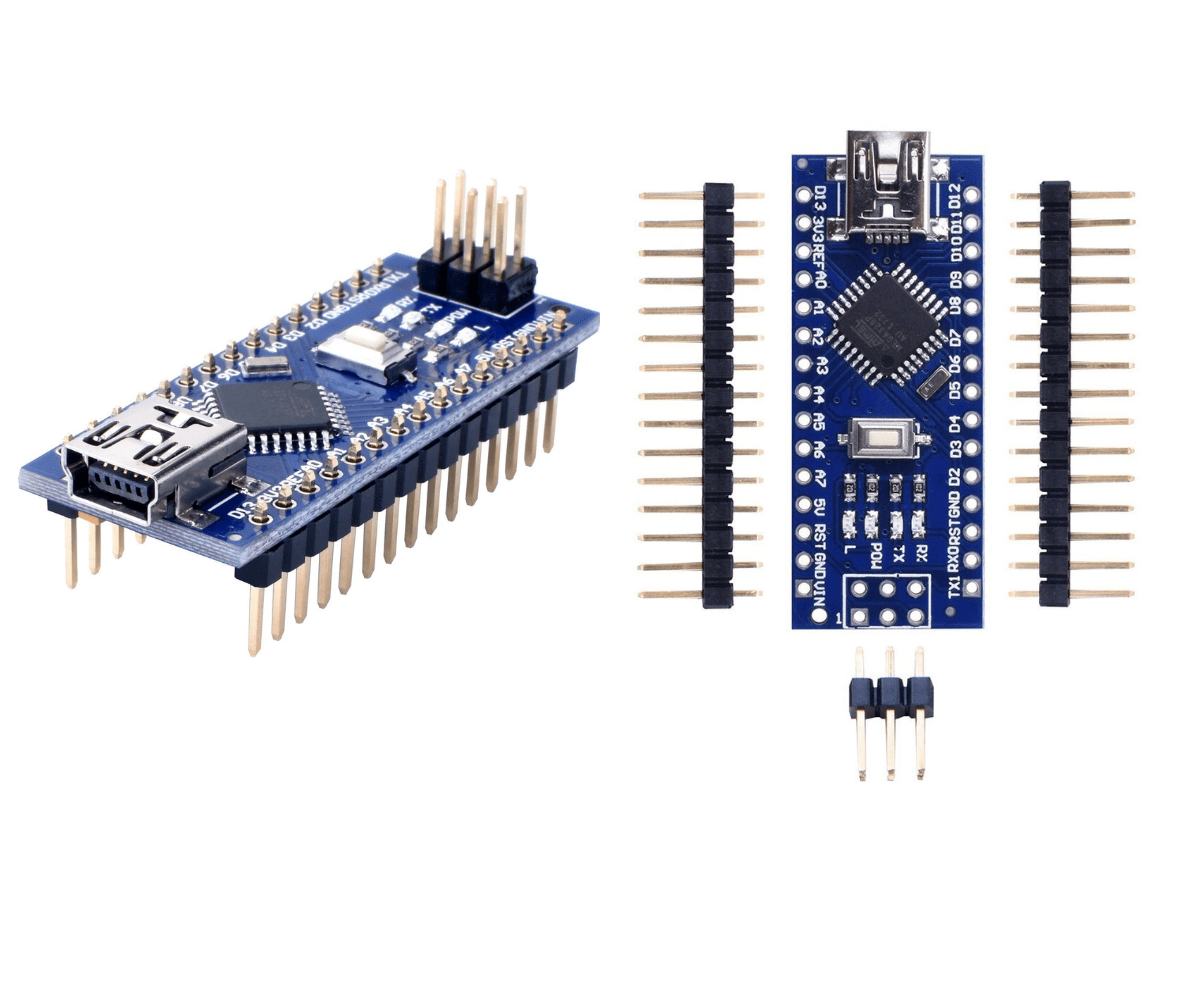
    https://kunkune.co.uk/shop/compatibl...le-atmega328p/


    Thanks!
    Unplug the Nano from the PCB and connect 12V between VIN (pin 30) and GND (either 4 or 29).
    Then measure the +5V pin (27). If you measure 5V, then the Nano power supply is OK.

    Leave a comment:


  • Qiaozhi
    replied
    Originally posted by Claes View Post
    Is there anyone who can help me to find the Arduino PI sketch which should be found on Geotech acc to George Overton.
    I am currently building the pulse induction metal detector described in his book with Arduino Nano.
    Many, many thanks in advance for your help !
    Claes.....recently member
    It's here -> Arduino Nano Pulse Induction Metal Detector Project - Published March 2021

    Leave a comment:


  • Claes
    replied
    Is there anyone who can help me to find the Arduino PI sketch which should be found on Geotech acc to George Overton.
    I am currently building the pulse induction metal detector described in his book with Arduino Nano.
    Many, many thanks in advance for your help !
    Claes.....recently member

    Leave a comment:


  • Lukelearning
    replied
    Hi guys

    I had the project working fine and was about to begin assembly when I started having issues with my nanos and the power that's burned out a couple of them out. Hoping someone can help before I kill my last one!

    The first nano just seemed to go unresponsive
    The second nano 5v pin measured about 7.5v
    The third nano from a different manufacturer had a VIN pin measured 12.5v and the 5v pin about 9v before burning out.

    i first thought it was just a dodgy batch but seems unlikely now.

    If helpful this is my third and last spare nano I have:

    https://kunkune.co.uk/shop/compatibl...le-atmega328p/


    Thanks!

    Leave a comment:


  • BrianBCB
    replied
    OK, obvious error, just in case anyone else makes the same mistake; the Hantek 6022BE only has a maximum input of+/- 5v (=/- 50v using 10x probe), so can't possibly measure the signal fully. With a very crude 100x attenuation now getting closer to 200v. Happy to proceed, did say I was rusty!

    Leave a comment:


  • BrianBCB
    replied
    Thanks Carl and Qiaozhi for your prompt replies, As you say scope is a PC-Oscilloscope (Hantek 6022BE), it had crossed my mind that the speed may be an issue. I'm tied up today but will try to look at the avalanche later; although I suspect that the speed may also be an issue in seeing that also. I guess I could proceed with project cautiously and come back to this stage if there is an issue.
    Thanks again for taking the time to reply.

    Leave a comment:


  • Qiaozhi
    replied
    Originally posted by BrianBCB View Post
    Hi
    Wonder if someone could help with a basic problem. I'm building the detector for our local heritage society (Stamford Bridge UK); I'm at Step 7 Transmit Circuit of excellent book but I'm only getting circa 50v flyback rather than 200v. I've checked resistance values, component polarities and orientation etc. Using 9" 24 turn hook up wire test coil, changing number of coil turns by 30% doesn't change flyback greatly, so suspect Q1 Mosfet is the problem or fault in board. Attached screenshot of osc reading using 10x probe, Vpp is only 60v.
    Apologies in advance if I'm missing something obvious, electronics experience very rusty!
    Thanks in advance
    What scope are you using? It looks a software-based unit, possibly connected to a sound card?
    Is it fast enough to capture the peak flyback, or maybe limiting the maximum input displayed?

    Leave a comment:


  • Carl-NC
    replied
    Try to zoom in on the flyback to see if it is avalanching. Here is a plot of avalanching vs non-avalanching:

    Click image for larger version

Name:	image.png
Views:	285
Size:	51.0 KB
ID:	433345

    Another way to tell is to vary the TX pulse width and see if it also alters the flyback peak.

    Leave a comment:


  • BrianBCB
    replied
    Hi
    Wonder if someone could help with a basic problem. I'm building the detector for our local heritage society (Stamford Bridge UK); I'm at Step 7 Transmit Circuit of excellent book but I'm only getting circa 50v flyback rather than 200v. I've checked resistance values, component polarities and orientation etc. Using 9" 24 turn hook up wire test coil, changing number of coil turns by 30% doesn't change flyback greatly, so suspect Q1 Mosfet is the problem or fault in board. Attached screenshot of osc reading using 10x probe, Vpp is only 60v.
    Apologies in advance if I'm missing something obvious, electronics experience very rusty!
    Thanks in advance
    Click image for larger version

Name:	Screenshot 2025-01-20 182327.jpg
Views:	258
Size:	129.3 KB
ID:	433341

    Leave a comment:


  • GeoMax
    replied
    Thanks for the link....

    Leave a comment:


  • Myntmaster
    replied

    €14.50 | ESHANG A4 10 Sheets Premium Printable Vinyl Sticker Paper for Inkjet Printer Matte White Waterproof,Quickly Dry 8.3×11.7 Inches
    https://a.aliexpress.com/_EJkFFkC
    —-------------------
    ​I print on an inkjet printer on this basis. Sufficiently wear-resistant. I think there is something similar for a laser printer.

    I’ll explain how I made waterproof terminals for potentiometers and switches one of these days. It needs to be explained with a drawing.​

    Leave a comment:


  • GeoMax
    replied
    Originally posted by Myntmaster View Post
    Front panel. The detector can be used underwater.
    Aliexpress sells a special A4 film. She's like a sticker. You can print on a regular inkjet printer. Does not wash off or wash off later. We print what you need and stick it on.​
    Nice job!!! Looks really good. Can you post the Aliexpress link for that special A4 film paper? And can you also use this paper with a colour laser printer?
    How have you made your potentiometers water proof for diving?

    Leave a comment:


  • Myntmaster
    replied

    Thank you. These guys are pros. The resistance of resistors can differ by smell.

    Leave a comment:

Working...
X