Announcement

Collapse
No announcement yet.

Arduino Nano PI Main Discussion

Collapse
X
 
  • Filter
  • Time
  • Show
Clear All
new posts

  • Gunghouk
    replied
    Originally posted by SaltyDog View Post

    I was asking a question of Gunghouk, different discussion, try not to be so sensitive ..
    To answer your question the aim was to standardise the software loop time and ISR times to allow the ISR to complete without interrupting itself thus causing jitter. Most of the ISR time was spent bit banging the outputs, hence fast digital write instead. While attempting that it became obvious that other sections of code were adding to loop time, such as floating point maths in the pulse timing routine. So in for a penny.... I eliminated conditional statements as stated in the comments and used integer variables wherever possible. As stated by Teleno it is not about absolute accuracy but more about consistancy in pulse timing by hardware (preferred) and/or software.

    Leave a comment:


  • SaltyDog
    replied
    Originally posted by Teleno View Post

    You can make very precise calculations but at the end of the day if you toggle the pin by software (bit-banging with digitalWrite()), especially inside an interrupt, you have to add the latencies which are not constant. The actual pulses will vary in timing from one period to the other, depending on which instruction is being interrupted. These vatiations are called jitter, and result in higher noise and loss of sensitivity.

    You want to control the pulses by hardware with the precision of the crystal clock, which is not a problem because Atmega328P has the right peripheral to do the job.

    Why not take andvantage of it? It also results in cleaner code and you don't have to mess wth offsets.

    But I'm not forcing you, just giving you a choice for FREE. No thanks!
    I was asking a question of Gunghouk, different discussion, try not to be so sensitive ..

    Leave a comment:


  • Teleno
    replied
    Originally posted by SaltyDog View Post

    So I did the calculations, why the such precise timing? I don't see the need?
    You can make very precise calculations but at the end of the day if you toggle the pin by software (bit-banging with digitalWrite()), especially inside an interrupt, you have to add the latencies which are not constant. The actual pulses will vary in timing from one period to the other, depending on which instruction is being interrupted. These vatiations are called jitter, and result in higher noise and loss of sensitivity.

    You want to control the pulses by hardware with the precision of the crystal clock, which is not a problem because Atmega328P has the right peripheral to do the job.

    Why not take andvantage of it? It also results in cleaner code and you don't have to mess wth offsets.

    But I'm not forcing you, just giving you a choice for FREE. No thanks!

    Leave a comment:


  • SaltyDog
    replied
    Originally posted by Gunghouk View Post
    1 = 1/16 Mhz = 62.5 nS so multiply those offset values by 62.5nS to give uS.
    So I did the calculations, why the such precise timing? I don't see the need?
    word TxOnOffset = -40; // TX-on pulse width offset (2.5us)
    word MainDelayOffset = -36; // Main sample pulse delay offset (2.25us)
    word MainSampleOffset = -41; // Main sample pulse width offset (2.56us)
    word EfeDelayOffset = -118; // EFE pulse delay offset (7.38us)
    word EfeSampleOffset = -42; // EFE pulse width offset (2.63us)
    word TxPeriodOffset = -241; // TX period offset (15.1us)​

    Leave a comment:


  • Teleno
    replied
    Originally posted by Teleno View Post

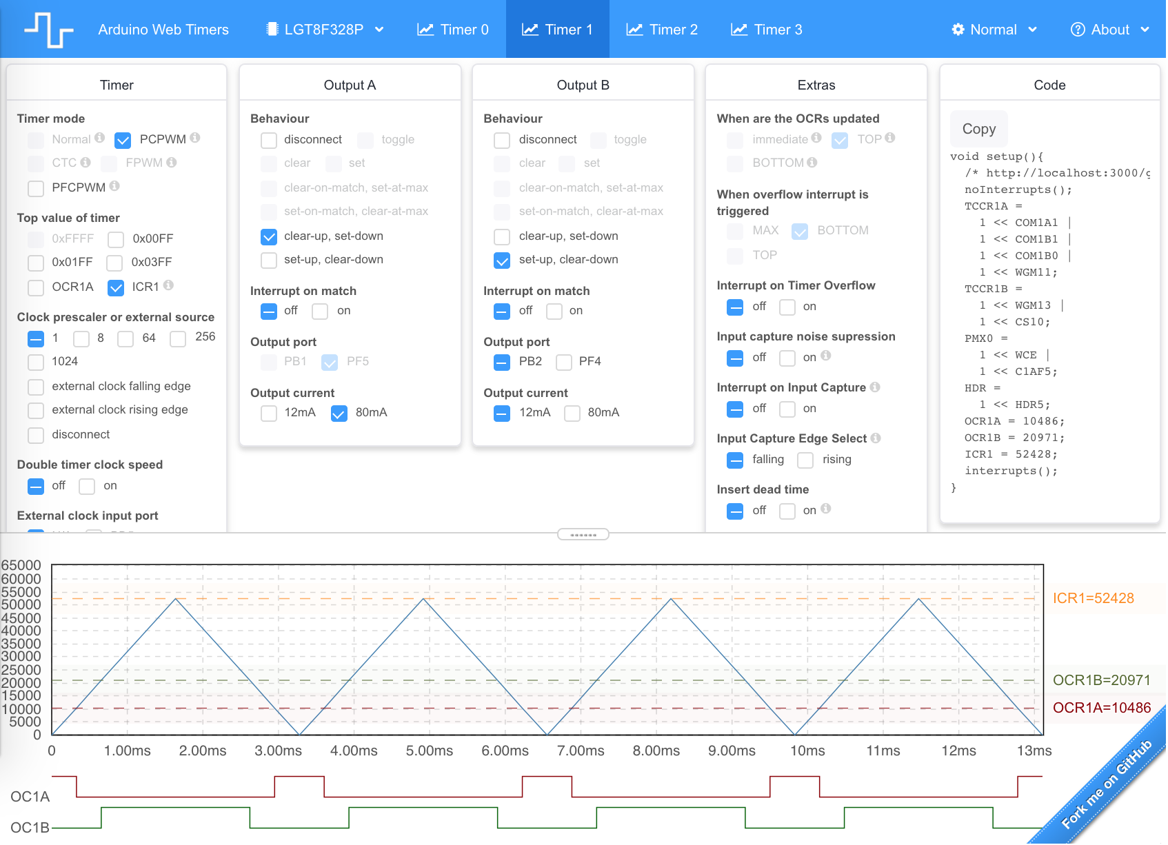
    The way to generate precise pulses is to configure a timer to drive a PWM output.
    I've added a sketch that applies this more precise timing method.

    This version drives the Tx and mainSample pins using two PWM outputs of Timer1 rather than driving them "manually" with digitalWrite(). The duration of the corresponding pulses is jitter free and can be changed in exact increments of the system clock period (62.5 ns). Since TImer1 only has two separate PWM outputs,

    Leave a comment:


  • Gunghouk
    replied
    Nice. Mine is still bare bones awaiting the time and energy to actually test with the assortment of coils I've built or acquired.

    Leave a comment:


  • SaltyDog
    replied
    Click image for larger version  Name:	IMG_20240208_185627937.jpg Views:	0 Size:	545.2 KB ID:	420001Here is what my unit looks like. Also, I managed 40cm with my gold ring.
    The case is a waterproof clam-shell with an over-center clamp, and an o-ring seal.
    The handle is a cutdown walking stick ... just perfect ..
    Attached Files

    Leave a comment:


  • SaltyDog
    replied
    Originally posted by Gunghouk View Post
    Yep, that was better, thanks.

    Leave a comment:


  • Teleno
    replied
    Originally posted by Teleno View Post

    The way to generate precise pulses is to configure a timer to drive a PWM output.
    This is the best tool I know of.

    Application to configure and visualise timers. Support for Atmel atmega328p (e.g Arduino Uno, Nano, Pro-mini) and Logic Green lgt8f328p. PWM, FPWM, CTC, PCPWM, PFCPWM, Interrupts, Dead Time, Prescalers, Capture and more.

    Leave a comment:


  • Teleno
    replied
    Originally posted by Gunghouk View Post

    Or divide the number by 16 to get uS

    Using clock cycles allows precision down to 62.5nS when tuning the pulse waveforms with an oscilloscope.
    The way to generate precise pulses is to configure a timer to drive a PWM output.

    Leave a comment:


  • Gunghouk
    replied
    Originally posted by Gunghouk View Post
    1 = 1/16 Mhz = 62.5 nS so multiply those offset values by 62.5nS to give uS.

    The first line of the comments says exactly this.

    Just Google digitalWriteFast.h to find the library and add it to your arduino library folder.
    Or divide the number by 16 to get uS

    Using clock cycles allows precision down to 62.5nS when tuning the pulse waveforms with an oscilloscope.

    Leave a comment:


  • Gunghouk
    replied
    digitalWriteFast-1.2.0.zip

    OK this is from the Arduino site.

    Attached Files

    Leave a comment:


  • SaltyDog
    replied
    Originally posted by Gunghouk View Post
    1 = 1/16 Mhz = 62.5 nS so multiply those offset values by 62.5nS to give uS.

    The first line of the comments says exactly this.

    Just Google digitalWriteFast.h to find the library and add it to your arduino library folder.
    Ok, tried the included file digitalWriteFast.h, but get this on compile:
    /Users/bernardmentink/My_Work/Arduino/arduino_PI/arduino_PI.ino:112:7: note: in expansion of macro 'digitalWriteFast'
    digitalWriteFast(txPin, mosfetOn); // Turn on Mosfet
    ^~~~~~~~~~~~~~~~
    /Users/bernardmentink/My_Work/Arduino/arduino_PI/digitalWriteFast.h:316:18: error: call to 'NonConstantUsed' declared with attribute error:
    NonConstantUsed(); \​

    Leave a comment:


  • Gunghouk
    replied
    digitalWriteFast-master.zip

    Here it is anyway.

    Leave a comment:


  • Gunghouk
    replied
    1 = 1/16 Mhz = 62.5 nS so multiply those offset values by 62.5nS to give uS.

    The first line of the comments says exactly this.

    Just Google digitalWriteFast.h to find the library and add it to your arduino library folder.

    Leave a comment:

Working...
X