Announcement

Collapse
No announcement yet.

Noiseless power supply for SD2200V2?

Collapse
X
 
  • Filter
  • Time
  • Show
Clear All
new posts

  • #46
    [QUOTE=BillNEWAST;147106]bkline, what is the difference between the floppy/hdd cable an the stock item minelab puts on. I can't see any difference in the amount of copper in the two. I think that minelab just used that type of cable because they got a GOOD Deal on it and it did the job adequitley. I think that is like the Battery system they used. At the time that was the Best Off The Shelf system to use. It had Nothing to do with "WAS It the Best".

    .QUOTE]

    Hi Bill,
    I used the twinlead from power adapters I work with at work. This uses 22AWG wire (IDE uses 28-30AWG). It is a close fit to the hole. It is easy to strip - really easy to do it without accidentally cutting some of the stranded wires. I cleaned the holes up really well and then stripped the wire ends like and eighth of an inch or so and inserted them into the holes without tinning them. When I tried tinning them I found that sometimes solder would exceed the hole size. So once inserting them succesfully in the holes I put a dab of rosin on each and soldered them. Trimmed em up and then cleaned off the rosin residue. I work at Western Digital so I have a bunch of old IDE cables I could have used. I'm not saying they won't work but here's another point: when you use a ribbon cable it is easy if not careful (like me) to put stress on the end wires when you insert or remove the boards from the extrusion by pushing one then the other. With the twinleads, each pair is separate so you can get away with it without risk of breaking wires. So they may be ok if you strip them back into pairs for the first 1/2"-1" each end. The original Minelab ribbons are just an accident waiting to happen as opening the two boards apart or pushing one pcb in then the other is likely to cause breakage of the stranded wires. I suppose if there were silicone at the attach point it would help prevent this. My experience with IDE cable ribbon is that it is difficult to do all 20 strippings necessary without screwing up and cutting some strands of some. Then inserting all 10 at a time vs my 2 is another challenge. I wouldn't advise anyone to mess with the ribbons unless they determine there is an intermittant or broken wire. Just be thoughtful about the hazards of pcb manipulation. There could be signal quality issues involved too that made Minelab chose the ribbons they did - mine may be inappropriate and thinner wire better. Just don't know because I don't know the schematic of the cables.

    Comment


    • #47
      bkline, Then what would probably be just as good is to buy a spool of 24AWG wire and then wire in individually? We don't have access to your resources, so must consider alternatives. Remember we have many folks from Forigen countrys who read these posts and do not have access to our resources in the US. I try to think of what is readely avaiable everywhere.

      sincerely
      Bill Adams

      Comment


      • #48
        Originally posted by BillNEWAST View Post
        bkline, Then what would probably be just as good is to buy a spool of 24AWG wire and then wire in individually? We don't have access to your resources, so must consider alternatives. Remember we have many folks from Forigen countrys who read these posts and do not have access to our resources in the US. I try to think of what is readely avaiable everywhere.

        sincerely
        Bill Adams
        Kind of difficult to see how some one who paid a couple US $1ks for this detector not have access to $5 wire.

        Comment


        • #49
          Mario, I was refering to bkline's use of power supply cable/wire from his work scrap pile, he had made the comment about floppy cable molex not being heavy enough. I do not have accesess to his goody pile from his work. Thats all I ment about not having the resources for the job. There is an additional componet that I always try to recknoize and that is there are hundreds of folks who lurk here that are from foreighn countrys and DO Not have access to Our ease of Supply. When I was gold mining in Peru in the early '80s you had to wait 3-8 weeks to get simple things like spark plugs for the dredges and If you had bigger Equipt. it could be months before you got your parts and was running again. Almost Noone in the US has a clue what its like to work in 3rd world countries and get stuff done.

          BA

          Comment


          • #50
            G'day Guys,

            For the ribbon cables between the boards, before changing them I would want to be certain that it was faulty. Solder a wire to both sides of the ribbon cable and then test for continuity while wriggling the boards.

            I don't know that using ribbon cable for a hdd is the best. The wires are very close together. Perhaps you could ground every 2nd strand. The original ones have a decent space between each trace. The other alternative would be to make your own! Just use some normal hookup wire spaced evenly and hold in place with packing tape on either side. Or if you want to get really fancy you could use silicon or polyurethane to make a new cable. As long as the wires are unable to move around in relation to each other when the machine is bumped.

            Use some hot glue where it attaches to the board to prevent stress on the end of the wire when it vibrates or is opened up etc.

            Cheers Mick

            Comment


            • #51
              Mine works, I hope I only have to open it to add some cool GP Extreme mod to make it as good as a GPX-5000....
              As far as power adapter cables... Come on Bill. This is getting silly.
              Any stranded wire is ok if your ribbon is compromised like mine was. Just look for easy.
              For me that was using twinlead wire from power adapters. The world is full of people with cellphones and chargers that use twinlead wire. Let's move on.

              Comment


              • #52
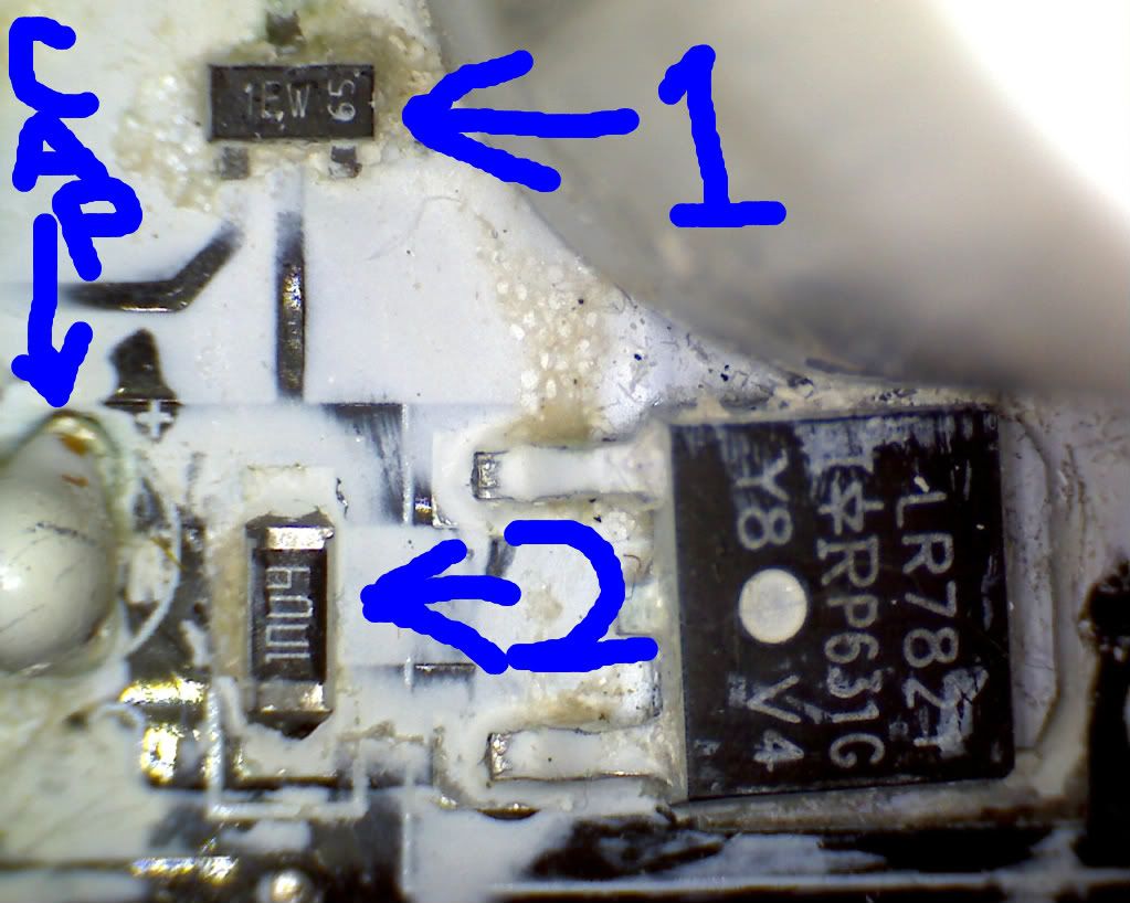
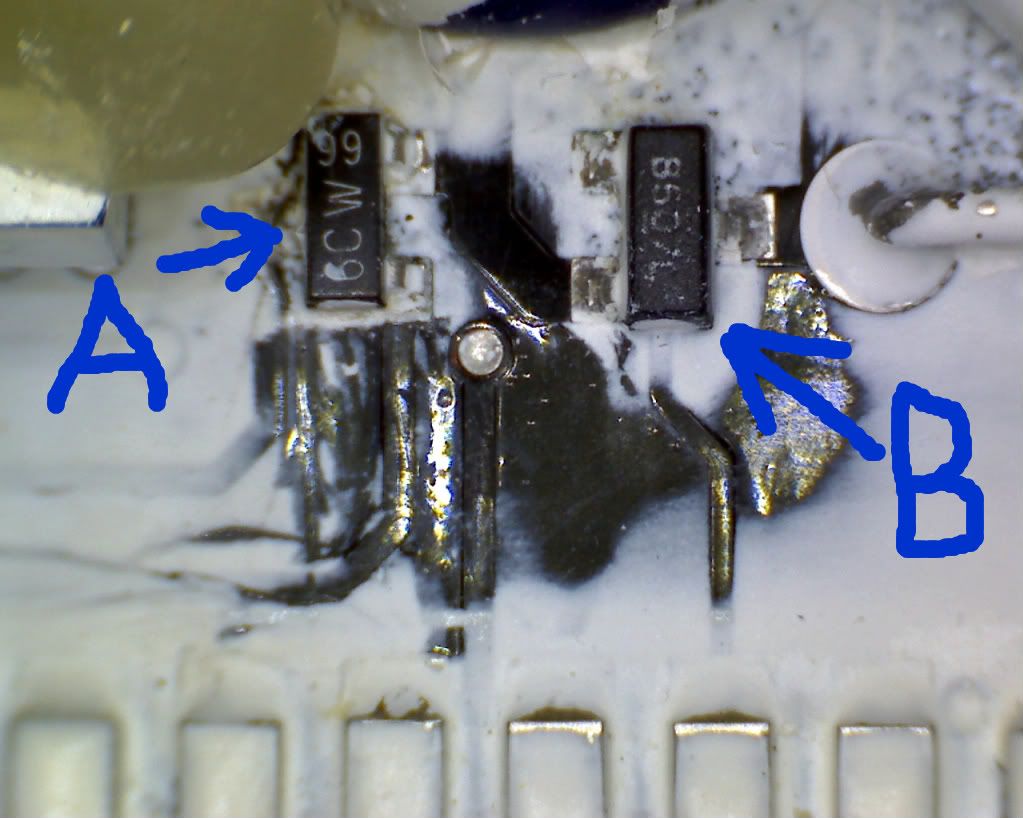
                I agree bkline, so here is the pics I promised last week!!


                #1 is the fet Woody was talking about I think, IRLML0060TRPBF, BUT HAVEN'T CONFIRMED YET.
                #2 is a resistor with a measured value of 985K.


                A is not the one??? The #1 in your pic mario I don't want to take the time to clean off yet.
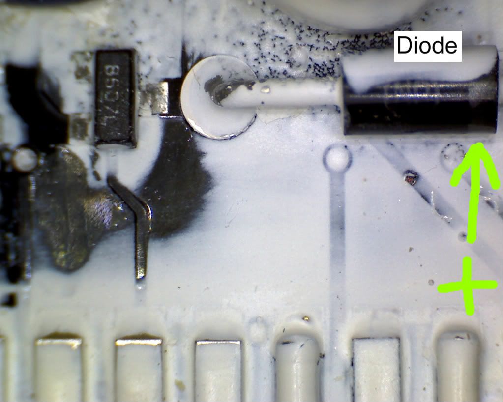
                I think the #3 in yours (B in mine) is the one that connects to the diode in the next pic.

                My eyes are too poor to be able to see with out the microscope set up and then I can't get the probes and other crap all setup to take measurments also. I didn't realize how much my macular degeneration would hinder this endeaver. I'ts been some time since I tried to do any real closeup work like this and I'm just realizing how bad it's gotten.


                and this is selfexplainatory above.

                mario how do you reaconize and or Identify the parts when they are SMT pieces. The numbers don't cross reference until you know the part # and then the numbers on the SMT part are just the date codes and such???
                Is the part number under the black solder mask? This isn't like in the 1980's and 90's everything's different, or I'm too old and ignerant!!!

                Comment


                • #53
                  I believe the 6CW is a SOT23 - BC817 or SOT323 - BC817W


                  ;
                  45 V , 500 mA and are NPN general-purpose transistor

                  The 1EW should be a BC847 SOT23/SOT323 -

                  45 V, 100 mA NPN general-purpose transistor

                  I couldn't make out the other SOT23 chip numbers. Maybe you can.

                  Info taken from www(dot)s-manuals(dot)com website. (replace the dots with a .)
                  Select on the left side marking smd selection and it brings up a table to select from.
                  Hope this helps.

                  /r
                  jonn (aka Jiminy)


                  Comment


                  • #54
                    Bill,
                    Perhaps we should discuss the consequences of running your detector off higher voltage batteries. First off, it is not the way to gain longevity. Paralleling batteries for more Ah is the way to do that. Next, each type of battery has its own discharge voltage curve. Lipoly's are nice in that the voltage remains pretty constant until they die. This keeps all your control settings fairly fixed over time. Other types may continually drop in voltage forcing you to constantly check your control settings.
                    You should also check your detector performance with a lab/bench power supply over the voltage range you intend to see just what the behavior is.
                    I still come back to recommending the switching converter perhaps along with a fuel gauge design. Unfortunately the fuel gauge has to accompany the battery though so its a bit of a pain to develop. Without it you just have to expect things to die suddenly after normal period of use. Still better than using a different battery type and running at an undervoltage perhaps resulting in poor performance.
                    The some of the parts you are looking at may be held to the board with a SMT epoxy/glue so it is not trivial to remove them - you really risk damage to the pcb traces. As Jonn's example shows, there are typically 2 or 3 character codes that sometimes are described in part datasheets as markers. I found a website in China/Taiwan somewhere that listed a lot of these (don't remember where it was offhand).

                    Comment


                    • #55
                      jiminy, thanks for the info. It's just what is needed by me anyway, I didn't know where or how to find the CrossReference #'s for the SMT stuff.
                      the IC (B) is a SOT23-85 0 7L with an overscore and underscore on the 0.

                      bklien, IF you could find that china site with the # x rf, I'm sure Everyone here would be grateful.
                      The larger VDC supply was just a brainfart that Passed with the more useful info and thoughts that had substance (not $hit) pun intended. I think we all pretty much agreed that a larger source would intro noise in through the bucking converter.

                      What I didn't hear much about is whether the Existing Onboard supply cct had any dampening capacity to ruduce noise built into it.

                      Like I said earlier I'm back to designing a multibattery pack, using 7-8VDC Video Camcorder Batterys. There is a Bazillion of them out there that are becomming cheaper as time goes by, and the video cam manufactures Change sizes and formfactors on the newer models.

                      I have to get ready to do a Movie Shoot over the next Two weedends and I don't think I'll be doing much with the SD2200V2 until I get this out of the way.

                      I'll be cheacking back off and on to keep updated on the thread.

                      If no one has any other questions or wants closeup shots of the SD2200V2 CCT BRD;

                      I'll be buttoning it back up in a couple of weeks, to get ready for the Mining Season.

                      Thanks for all who helped and participated with this thread.

                      I still think that if more folks had participated and put their 2c's worth in we could have gotten modified SD2100V2 CCT Schema drawn, and published for everyone to use.
                      I know that there has to be more people who could contribute something no matter how small the info may seem.

                      There are 2,500+ views on this thread and the next one down. Then there are the threads that have 56,788 and 17,207 views. SO SOMEONE Needs to take the BIG LEAP and jump right in on the discussions and STOP just Lurking. GET Brave and Bold and take a Chance, we promise we'll be gentle. Ha Ha.

                      Sincerely
                      Bill Adams

                      Comment


                      • #56
                        Originally posted by BillNEWAST View Post
                        Like I said earlier I'm back to designing a multibattery pack, using 7-8VDC Video Camcorder Batterys. There is a Bazillion of them out there that are becomming cheaper as time goes by, and the video cam manufactures Change sizes and formfactors on the newer models.
                        Yeah, my pocket rocket uses the camcorder batteries - which are lipoly. I checked out the Pocket Rocket adapter for them and it does have a nice slow start with no overvoltage. A simple thing to make on your own using something like the part I mentioned earlier. Replacement batteries on Ebay were $20 and AC/DC chargers ~$5. But the chargers are SLOW. I plan to make an adapter using one of them to connect to my RC Lipoly charger where I can set the charge rate for faster charging times when I'm in a pinch.

                        Comment


                        • #57
                          bklien, I think that your idea of a fast charger is good. I do think that using 12Vdc source on the old MineLab 6Vdc dome top batterys is the Best Idea. The had a shut off circuit so they wouldn't run you rigs batt down past 11Vdc. I heard that if you left the minelab bat on the AC charger overnight that you could ruin the GelCell. I don't know if this is true as I NEVER charged mine on AC after the first initial charging when I got them.

                          I think that the circuit in the old Makita 9Vdc fast chargers would be a place to start, as you would only have to reset the Vdc out to the batterys you were charging. I don't know what the difference, if any, in charging the NiCad's vs the Lithium's would be. There is something like a Charge Discharge Cycle that is used to keep the Nicad batterys from overheating, but its been YEARS since I studied that stuff.

                          I had thought of using 4 or 5 Lithuim Cam Bats. at $20-25 ea. Then you have two with you detecting and are carrying a spare for that Last boost on that patch you found at dusk and just can't go back to the Rig till you are faint from HUNGER and NO more FlashLight left. It can also be used for a Flashlight to get you back to the rig in the DARK.

                          The other two are on the charger at the rig. I carry at least 1 and most times two 12Vdc DeepCycle RV Batteries to charge my Detector Batteries with. The also run my 400W inverter for the laptop and any other gagets i have along. I record the days GPS Tracks and waypoints onto Topos at night and plan my next days detecting off the Geo Maps.
                          BUT, I also don't just go out for the DAY either. My trips are for 2-3 weeks at a time, so I have to be Very Mobile. I usually go to a nearby town once a week or so depending on how remote I'm at.

                          Each person will have to make a decision on how his/her Charging Needs are. IE only day trips or extended trips. Like on Day trips you would only need 3 Lithium bats, two on the detector and one as a backup. For extended trips, or group day events, you would need a charging station that would accomadate at least 2 or 3 batterys at a time.

                          AND, bklien have you Run accross that China Site with the SMT Cross Xrf numbers?
                          Well enough for now.
                          Sincerley
                          Bill Adams

                          Comment


                          • #58
                            Originally posted by BillNEWAST View Post
                            ...
                            There are 2,500+ views on this thread and the next one down. Then there are the threads that have 56,788 and 17,207 views. SO SOMEONE Needs to take the BIG LEAP and jump right in on the discussions and STOP just Lurking. GET Brave and Bold and take a Chance, we promise we'll be gentle. Ha Ha.

                            Sincerely
                            Bill Adams
                            Hi Bill, people show interest in these Minelabs because they continue to be good equipment in spite of their no longer being cutting edge.

                            A lot of behind-the-scenes work has been done to correct the shortcomings of these detectors, and people continue to improve them in private.

                            In public, however, people hesitate to share their projects because so many individuals have already being screwed.

                            When I first started several years back, very few people shared information about these detectors. I think, over the years, things have become better, but when it comes to public information, we are nowhere near we could be when we compare the openness that exists with other detectors.

                            Having said that, don't give up hope. It's not every day we come on here, so I wouldn't be surprised if some one drops in from time to time and makes suggestions.

                            In regards to your 2N7002 fet, have you taken a look at Zed's schematic for the SD2000? It should be here: http://www.geotech1.com/forums/showthread.php?t=14001

                            If you look at page 2 of part 2, you will get an idea of what needs to be replaced. The SD2000 uses 2N7000, yours uses 2N7002 (mine uses ZVN2106).

                            Most mods come with risks so I would strongly advice you to consider them carefully before performing them. For instance, the voltage mod you're considering is something I would never attempt with my SD2100V2.

                            Why? Well, after checking out the several datasheets of the components we have identified on the main board, I have noticed that several ICs used by Minelab are running near the upper limit of their voltage ratings (on the logic cct).

                            Is it worth the risk?

                            Comment


                            • #59
                              Turns out that there are a ton of sites with transistor identifier codes. I must have used the wrong search terms on Google earlier. Just try "SMD" and "marking codes" and you get a bunch. Here are a few:

                              http://www.digikey.com/Web%20Export/...f?redirected=1

                              http://www.angelfire.com/electronic2/rch/smt0.html

                              http://www.marsport.org.uk/smd/mainframe.htm

                              http://www.turuta.md/demobook/SMD-2010_sample.pdf

                              Comment


                              • #60
                                Thank You mario, I have already come to that conclusion myself. I haven't been able to generate enough specifications and data for the 22xxv2 to start replacing parts that I haven't been able to positivly ID yet. If I had more time (like next winter) I may decide to finish stripping the paint off the boards and setup the O-scope and do some back engineering to find the values. I won't do that this year though as it's almost time to nugget hunt. Snows almost gone in my areas.
                                I know that most folks who have done the back enginerring on these detectors are making a living or at least supplemnting their income with repairing or MODing them.

                                If I had taken the time to compleatly back engineer the 22xxv2 with schematics and volt and timming values, I would be Hesitant to SHARE this info with anyone on a public forum. I probably would share the info with select folks by Private Email though.

                                But just think of all the business that you could get if you were a Repair Tech. and let the info out for the Mass's to $crew up their detectors with.

                                Thank You VERY Much bklien for your Help on defining the parameters to find the SMT parts Number Xrf's, I had tried using the old IC searchs and didn't find anytheing.
                                AND another thank you to jiminy for your contribution.

                                Well got to get ready for the movie shoot tomorrow.
                                Sincerely
                                Bill Adams

                                Comment

                                Working...
                                X