hi friends
can any one help to to make a coil for deltapulse3 ?
i have only 0.5 Copper cable.
-
hi purklovr
i will check it, thank you
do you have information for minelab or one detector sence only gold ?Leave a comment:
-
You'd better disconnect the FET from 12V drain power and make sure your 556 is working properly. Removing the coil should be sufficient.Originally posted by alonejax View Post
Your current draw should then reduce to about 5~10mA (just a guess).
Place your multimeter lead on ground, then you should measure about -6V on 556-5 and 556-9. Those pins' voltages should increase slightly as you rotate each's associated potentiometer clockwise. (PPS changes 556-5 voltage, and PW changes 556-9 voltage).
If you have a frequency meter, you may be able to see frequency changing on 556-5 and 556-9 as you rotate the PPS pot. These two pins' signal duty cycle may be too low for reliable triggering on your F-meter, but try it anyway.Leave a comment:
-
thanks purklovr
my battery is 12v 4a dry battery
when i start give me 4.12Amper and my irfp460 is hot, is normaly?
i dont think my battery low
thanks alotLeave a comment:
-
Your "noise" pot can be more descriptively called the Pulse Width (PW) pot.Originally posted by maximusdesmus View Post
The Red LED's normal function is to illuminates when your battery is weak, needing recharged.
But also, for any transmitted PPS (Pulses Per Second) setting, there will be some value of PW that will cause current consumption to exceed the battery's current delivering capacity. When that happens, the battery voltages drops, and the red LED will illuminate. That is telling you to reduce either PPS or PW, reducing battery consumption to a more reasonable value. Or, you could instead decide to live dangerously, and use a bigger battery... but in the case of your FET getting hot that is not a good idea.
If you have a milliammeter, connect it in series with your DP and the battery. Watch what happens as you change the PPS and PW controls. I have read that a reasonable maximum value of battery current to prevent the FET damage is somewhere around 150mA.
If you want to be able to have 100% usable range on your PW pot and you know the maximum PPS that you will ever use, you could set maximum PPS, and then modify the value of the PW pot to eliminate your unusable zone. Reducing the value of PW pot (or paralleling a fixed resistor across the pot) will reduce the maximum pulse-width. But you must first determine maximum desired PPS.
If you want to keep the full range of PPS but also keep the full range of PW, then you will simply have to accept the fact that you cannot use maximum PW and maximum PPS at the same time.
Increasing the value of PPS pot (or R1) reduces maximum PPS frequency.
Decreasing the value of PW pot (or C3) reduces maximum Pulse Width.Leave a comment:
-
hi to all
i made this delta pulse but dosnt work
i have sound , 250 hz & 19 cm coil 30 turn 0.45 with 3.4 ohm
i used 12v 4A for sourc capacitor
first i have coil with 15 turn of .45 with 2.5 ohm but when i start multimeter show 4Amper use! and
my red led & green led was on. i turn off fast
then i chang my coil to 19 cm coil 30 turn 0.45 with 3.4 ohm.
now my delta is on & have sound but dont sence any thing
i used lf357 & irfp460
please help me. thanks a lot
[email protected]Leave a comment:
-
I have a problem with my delta pulse pcb.The coil is 28cm 2.5ohms i detect gold ring at 23cm in air,one euro coin 25cm clear signal,coke can 45cm,paint can 57cm.
Detector works well except one problem and i post video of lcd together with the picture of my pcb.
The problem is when i turn noise pot over the first half of the whole turn for better detection the red led also brightens up and detector just beeps once then gets silent and stops detecting and irf740 starts warming, so when i turn the noise to lower again it starts working normally.
Also one more thing that may be important the 9v1 zener gives me 8.85v when working normally and 8.2 when this problem occurs.
Dumper is 1K.
I have looked for mistakes on my pcb but couldnt find any.
I gratefully hope someone on this forum can help me fix this ,here are the pics and vid. of delt working normally when noise is not high:

Leave a comment:
-
Who can help me delta I do pulse no depth of 32*35 box,1MM line 1M*1M=16 ring coil. Only 150CM can be detected, R1 470K C1 22NF. 125HZ. How to adjust the frequency without userLeave a comment:
-
HELLO, anyone can tell me where to find this circuit LAY format?
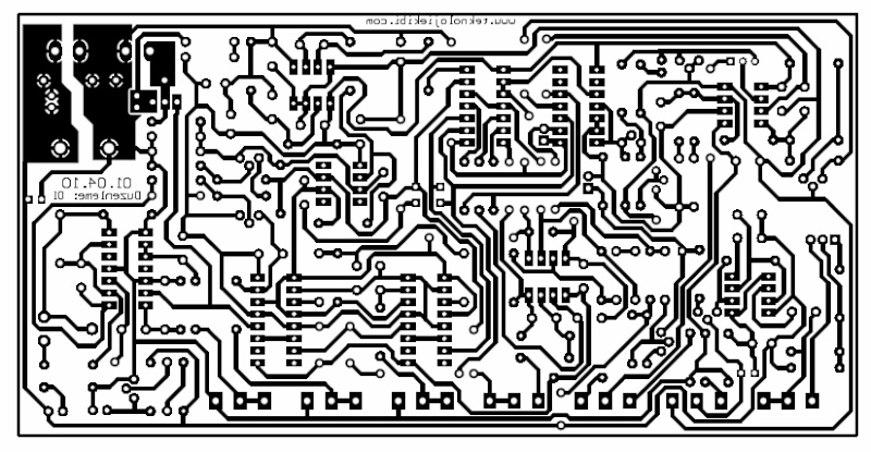
thanksLeave a comment:
-
nando.22
Using the diagram on page 78, Post No. 1932, C31 and C32 is mf 4700, is susficiente.
Otherwise, you can place two capacitors in parallel mF 4700 (2X4700).
Follow the advice of KT315, place a plate blindage the under PCB, as seen in the post Nº 1528, the detector is more stable especially with coils 1X1 m.
regards JoseLeave a comment:


Leave a comment: