My delta pulse rev 5 is not detecting anything and beeping nonstop.I have checked voltage on +E 12v and -E 11.78v. T2 is tuned to 100Hzs.
The problem started when due to poor detection depth i installed DSEI1210A diode and changed 100v ceramic capacitors C23, C24, C19, C20, C14, C15, C11, C9, C8 with 100v polyester due to poor. I have changed all ICs Replaced ceramic capacitors but the problem
Thank you
-
Hi to all!
I spent 2 weeks to read all thread.
Amazing, this thread is already historical since it gose from 2004 year... wow i remember my school years
This place we already can call Deltapulseland
Most useful part was until 50 page, and after all useful info roll-down to "how-to" and "why" style. So that's seems to look
normal at nowedays)
I had successful build of DP and just interested to know what air distance it reach in other deltapulsers.
May anybody make a test at freetime, so we all can see results here?
Setup for test:
Target - aluminium can 0.5 liter, worldwide populatet.
Coil diameter 27-50 sm for indoor test.
Aditional info like current consumption will be good.
That's all.Leave a comment:
-
life hack from 315. set the LEDS on rear of uamperemeter, i mean the LEDs of voltage indicator.
you get - BLUE backlight in normal state of the batt, RED backlight in low state/discharge of the batt.
Leave a comment:
-
i suspect this/turkish layout has 2-3 fatal mistakes. if you need a success without electronics basic knowledge you certainly must use just checked layout copied in thousands pcs.Leave a comment:
-
i recently built single layer delta pulse
The detector produces very very long tone after detecting a target. Sometimes the tone is nonstop unless i use the reset button.
Has anyone else experienced the same thing? How this can be corrected?Leave a comment:
-
people very often set chips backward and get a headache. apply with red color paint/varnish (take it from females, they have them much)
points of 1st pin position. i use fluorescent one.
Leave a comment:
-
hi Tomek
1. I know that I should connect all pots with piece of wire. Shell I connect it also with E+ ?
if you do graphite layer on back side of face panel then you should not connect all pots by naked wire. throught you have to connect the layer
to shield point on pcb. for example by way doing Whites in their coils.
2. Shielding of housing. I have copper tape so as I understood I should glue this tape at the bottom (under board) and at the front panel. I would like to make sure that I should connect both copper surfaces with +E (comming from R59 as I can see on the schema) ?Rare panel, where I have battery should be also shielded and connected to point comming from R60?
if you do not have access to graphite powder you can do this way. you have to shield under the board. a sensitive place to static is front end preamp and second
stage mainly. rear panel is not needed to shield although you have to connect a connector enclosure to point R60 100 Ohm.
that way was copied from DEEPERS 10DD detector. pics 22 and 23 https://www.geotech1.com/forums/album.php?albumid=102
I'm at the moment not sure what is better to use connecting coil with housing:
- 2xAWG23 with shield (I have good experience in my first 2 detectors (VLF and PI)
- or maybe speaker 2 lines of 1.5mm without shield (I used it in my last PI detector which didn't work very stable).
for meter coil shielded cable is not needed. i took standart multiwire cable in fat isolation round type that using for 220 AC.
1. I would like to setup frequency with P.P.S.100k to 100Hz (regular in my country is 50Hz). Is it safe for DP electronics to turn on device without connected coil to setup frequency? All pots should be at MINIMUM level or it doesn't matter (while the coil is not connected) ?
visit especially made by me thread https://www.geotech1.com/forums/show...d-Interference
you can do all manipulation on board but onetime i got effect without coil. so i suggest to measure signals without MOSFET.
if you got right signals then solder it, connect small coil and test.
for first test positions of the pots has to be -
- DEPTH - min, at left side, counter-clockwise
- DISC - min, at left, counter-clockwise
- GEB - middle
- SENS - middle
- T/HOLD - middle
do not test big coil in your room/house/home.Leave a comment:
-
Hello, my DP is almost finished.
There are left just few things to do:
- clean the bottom of the board after soldering
- solder bottom tantalum capacitors
- insert integrated circuits
- connect board, battery, fuse and power suply port as well as connect board with coil port
- to make shielding
And in the last point I have some doubts:
1. I know that I should connect all pots with piece of wire. Shell I connect it also with E+ ?
2. Shielding of housing. I have copper tape so as I understood I should glue this tape at the bottom (under board) and at the front panel. I would like to make sure that I should connect both copper surfaces with +E (comming from R59 as I can see on the schema) ?Rare panel, where I have battery should be also shielded and connected to point comming from R60?
I couldn't get Graphite 33 in electronic shops, so the option is to order it on some e-shop.
Is it necessary to use grafite while shielding of housing with copper? If yes, is it important which layer is first (copper / graphite)?
Below you can find 2 photos of my DP.
I know that it is quite heavy, but anyway I decided to put big battery inside (I had one 7,2Ah), so there was no more place left in the housing (especially for uA meter).
For the coil I have 10m of cat6 cable (8xAWG23) so I think that good choice may be frame 1.6x1.6m. 1 turn of connected wires (8 windings) should have inductance approx. 440uH and resistance of about 3.3 ohm.
Maybe next week I will have opportunity to buy 12x1mm wire, so then I will make coil 80cm in diameter, 1 turn (12 windings) with serial 2 ohm/1W resistor, which inductance should be about 390uH and final resistance about 2.6 ohm.
I'm at the moment not sure what is better to use connecting coil with housing:
- 2xAWG23 with shield (I have good experience in my first 2 detectors (VLF and PI)
- or maybe speaker 2 lines of 1.5mm without shield (I used it in my last PI detector which didn't work very stable).
Probably I have to wait few days for initial test of my DP, but I have also some questions regarding this stage:
1. I would like to setup frequency with P.P.S.100k to 100Hz (regular in my country is 50Hz). Is it safe for DP electronics to turn on device without connected coil to setup frequency? All pots should be at MINIMUM level or it doesn't matter (while the coil is not connected) ?
2. On the photos of your DPs I saw, that there are large capacitors connected to battery. Shell I need them ?
Best Regards,
TomekLeave a comment:
-
its range is 200uA so a bit more than it shoul be
---
increase a bit R37 value more. thats standart situation in simplest circuit if you want more current in one place you have to
increase R in other one.Leave a comment:
-
Thanks for quick replies.
I agree - in old devices it is possible to find valuable, high quality parts.
Anyway few days ago I've ordered uAmeter. I think it was good opportunity because its cost was only about 1,2EUR so not too much. Even if I will not use it in this implementation (as its range is 200uA so a bit more than it shoul be) it is worth to have it for some future purposes.
I think I will try to add LCD display to my DP, but first of all I concentrate to finish basic working device.
All the best!
TomekLeave a comment:
-
But now I have question regarding R23-R26.
According to BOM they should be 4k70 0.1%. Unfortunately most of my resistors have a bit lower values (up to 3% less than nominal). I believe it is no problem for most of elements but I'm not sure how it is in this case. The best values I could find for R23 and R24 are 4k58 and for R25 and R26 4k56.
I've read all the posts in this thread and I remember that those elements were mentioned at least 2 times. I remember, it was said that R23 should be paired with R24 and R25 should be paired with R26. Unfortunately "search" does not help.
----
necessity of using the presicion pairs i see from schematic. certainly you can use 4k58 or/and 4k56 resistors.
also, you can choice them from 1% resistors, in the pairs. no difference you use 4.56 4.58 or 4.46 value.
search does not help, but on the schematic that noted by text by me. also written in BOM file.
---
By the occasion I have second question - I'm not sure if I would like to use microamperometer in my DP.
Reading forum I didn't catch what is adventage of using it.
----
umeter is just intensity meter. like you see bounty hunter4 with it or BH fast tracker without it.
i repeat again do not buy for DP nothing - take components from old boards.
you can find umeter in any tape recorder taken it from garbage can (look on it in your shop center. they have this special box for trash
electronics. it is near shop intrance.).
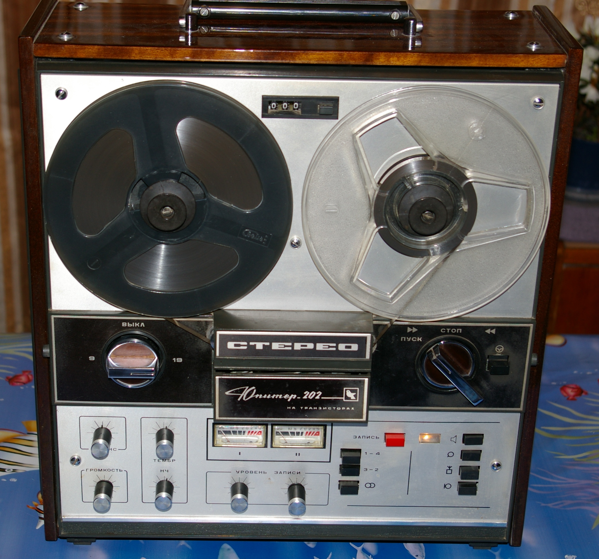
or, do not set umeter then you will get ugly delta pulse LOL.
---
when I won't use uAmeter than should I use jumper in PA1 slot? Looking at schema I guess that nothing is needed.
----
yup. nothing is needed. leave all-as-is.Leave a comment:
-
Absolute values of those four resistors is not the concern.
What is important is that the four resistors are all the same value or matched.
Just find four that are the same value to within 0.1% or 4.7Ohm of each other.
No idea about the uAmeter.Leave a comment:
-
Hello,
Recently I've bought a plate from KT, I've collected almost all elements and have started soldering. But now I have question regarding R23-R26.
According to BOM they should be 4k70 0.1%. Unfortunately most of my resistors have a bit lower values (up to 3% less than nominal). I believe it is no problem for most of elements but I'm not sure how it is in this case. The best values I could find for R23 and R24 are 4k58 and for R25 and R26 4k56.
I've read all the posts in this thread and I remember that those elements were mentioned at least 2 times. I remember, it was said that R23 should be paired with R24 and R25 should be paired with R26. Unfortunately "search" does not help.
So my question is if my values will be ok or I should better buy new one with required precision (0.1%)?
By the occasion I have second question - I'm not sure if I would like to use microamperometer in my DP.
Reading forum I didn't catch what is adventage of using it.
Maybe silly, but I have question: when I won't use uAmeter than should I use jumper in PA1 slot? Looking at schema I guess that nothing is needed.
Thanks in advance.
Best Regards,
TomekLeave a comment:


Leave a comment: