
Originally posted by mazari
View Post
-
thank you for all. do you think i'm using a wrong pcb?please correct meLeave a comment:
-
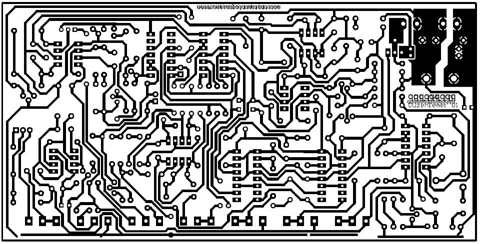
lots of closed lines on your board on bottom. i see only problems with your layout.Leave a comment:
-
1. Look for a short circuit between the paths on the board.
2. Look for a faulty element that can short-circuit.
The two LEDs indicate the presence of power and the voltage drops below the allowable minimum.
The second diode lights when the voltage drops. With a correct power supply, it can only light up when the circuit board is short-circuited.Leave a comment:
-
hi for all.please can any help me to find what would be the problem of my d.p it emit a continuous sound and the two leds are lighting.all ic and aop are good please help me. thank you in advanceLeave a comment:
-
for RED use a LED with forward/drop voltage 2,8-3V. ordinary LED with 1,5-2V drop voltage will give pale light.Leave a comment:
-
i had gave info how to shield case inside, WITH PICS, i also repeated that, do not think i must repeat
that again and again, for every new member.Leave a comment:
-
hI for all I have a problem with my Delta Plus2 (snifer xr-71)is when i tested on the ground gives a sound as if he found a metal interrupted for a few second and then sound returns again and so on. i tried to set but in vain .my coi lis=42cm diameter.0.5awg.resistance=3ohm .frequency =130hz .please can you help me to solve this problem .Thank you in advance
Leave a comment:
-
Second question KT315.
To supply with what battery is calculated module, which mentioned above - with lithium ion batteries, nickel metal hydride or lead acid battery. I ask because the subject of the elements red diode lights up at 7.9 volts. Then the green LED turns off.
If we change R53 from 16k and do it 10,5k, then red diode Highlights in at 10.6 volts, which is normal, if use lead-acid battery.Leave a comment:
-
the inscriptions on the board are proper. there are people who assemled all detector without problems.
P-CAD is very advanced soft, some kinda classic and standart for industry, with advanced error checking engine built-in.Leave a comment:
-
Thank you!
I continue to solder under the scheme. Do not be guided by the inscriptions on the board.Leave a comment:
-
you are smoky RIGHT, Toros! thank you! its mistake (((
you found a cause why this part did not work. (while it worked nice at my first DP, alien's PCB was, but i did it on breadboard)
issue. or to use 2N3904 mirrored setted either BC237 BC546 BC547 BC548 etc. CBE pinout type.Leave a comment:

Leave a comment: